

You are using an out of date browser. It may not display this or other websites correctly.
You should upgrade or use an alternative browser.
You should upgrade or use an alternative browser.
Fisher X-100 from hell
- Thread starter andy
- Start date


andy
Super Member
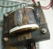
I have disassembled the transformer ready for the next step. Based on the number of turns on the heater windings, I'm looking at around 2000 turns for the B+ winding. I'll use my hand crack winding machine to unwind it for an exact count. From past experience, the biggest challenge will be getting the new windings to fit. I plan to use polyimide tape between layers, which should save some space compared to paper.
Attachments


Good luck with the rewind. That insulation is toast!I have disassembled the transformer ready for the next step. Based on the number of turns on the heater windings, I'm looking at around 2000 turns for the B+ winding. I'll use my hand crack winding machine to unwind it for an exact count. From past experience, the biggest challenge will be getting the new windings to fit. I plan to use polyimide tape between layers, which should save some space compared to paper.
You're probably going to need to look at the gut (read: rewind) the OPTs. too.

andy
Super Member
I unwound the B+ windings (counted 1969 turns). Much of the wire had the enamel literally falling off, but there were also large sections that looked like new. The insulation between layers was very thin and fragile paper.
One curious design choice was how the center tap was done. I would have expected the center tap to have been in the middle of the 1969 turns, and the two extreme ends would connect to the rectifier, but that's not what they did. The inner and outer ends were connected together as the center tap, and the two 360v outputs came from the middle of the winding. There was a layer of thick paper between the two middle ends, but that still seems like an odd way to do it since you have 720v RMS across that central insulation. Maybe that's normal; I haven't disassembled many power transformers.
One curious design choice was how the center tap was done. I would have expected the center tap to have been in the middle of the 1969 turns, and the two extreme ends would connect to the rectifier, but that's not what they did. The inner and outer ends were connected together as the center tap, and the two 360v outputs came from the middle of the winding. There was a layer of thick paper between the two middle ends, but that still seems like an odd way to do it since you have 720v RMS across that central insulation. Maybe that's normal; I haven't disassembled many power transformers.

andy
Super Member
It started as not even good enough to be a parts unit, but sometimes the challenge of resurrecting something like this can be fun. It's like restoring a car that's been in a field for decades.
I sprayed some insulating varnish into the output transformers to hopefully fortify the insulation. If rewinding the original power transformer isn't successful, I'll probably set it aside until I find a suitable replacement.
I sprayed some insulating varnish into the output transformers to hopefully fortify the insulation. If rewinding the original power transformer isn't successful, I'll probably set it aside until I find a suitable replacement.
andy
Super Member
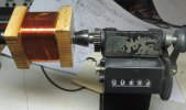
I've acquired all the materials, and I've started rewinding it. I've got 4 out of 16 layers done (123 turns per layer). So far so good, but it takes some time and care without an automatic winding machine. There isn't an extra mm left over on each layer, even when carefully aligning every turn.
Has anyone tried one of those Chinese $300 electronic winding machines on ebay? They look interesting, but I fear that poor documentation, and firmware bugs will make them useless.
Has anyone tried one of those Chinese $300 electronic winding machines on ebay? They look interesting, but I fear that poor documentation, and firmware bugs will make them useless.
Attachments
andy
Super Member
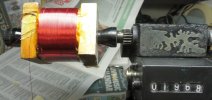
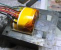
I've got all 1968 turns of wire on the bobbin, and there's plenty of room for the heater windings! I should know soon if it works. It wasn't that bad winding it, just time consuming (about 20 minutes per layer). Neatness was crucial. I sprayed each layer of windings with insulating varnish to hold things in place, and add some insulation, and then covered it with a layer of Kapton tape.
I can see why power transformer rewinding is expensive. First there's disassembly, and reverse engineering, which wasn't that hard since this one hadn't suffered a severe meltdown. The materials cost is quite high. I spent about $60 on magnet wire, and Kapton tape alone. I already had a spray can of insulating varnish, and one of the magnet wire sizes on hand, so I'm not counting those costs.
I can see why power transformer rewinding is expensive. First there's disassembly, and reverse engineering, which wasn't that hard since this one hadn't suffered a severe meltdown. The materials cost is quite high. I spent about $60 on magnet wire, and Kapton tape alone. I already had a spray can of insulating varnish, and one of the magnet wire sizes on hand, so I'm not counting those costs.
Attachments
andy
Super Member
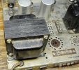
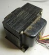
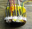
The transformer is finished (I hope). It all went back together without too much difficulty. I dunked the finished bobbin in some marine varnish to try to seal it, then inserted the laminations while it was still wet. It's outputting the correct voltages, and not making any noises. I've installed it on the chassis, but not wired it up yet.
Attachments

andy
Super Member
I put some tired old 7189's in, and a random 5R4 for testing, and after repairing a couple of broken wires, and working around a bad tube socket I have audio on both channels. There's a slight channel imbalance in the tone control circuit which is probably caused by the couplates. I also need to replace at least one tube socket since the terminals are so loose they're almost ready to fall out. So far the other sockets seem fine, but I may replace the rest depending on how things go.
Attachments
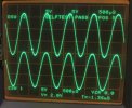
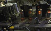

Call me impressed!

crispycircuit
Super Member
Impressive!!

andy
Super Member
So far it hasn't gotten too hot to touch. I don't expect temperature to be a problem. The materials I used should be significantly more heat resistant that it originally was. The failure I had wasn't caused by overheating, it was definitely water damage.Thank you for sharing, very interesting. How is the transformer doing temperaturewise? I think 210-220 F is normal for these right?
Today, I replaced one of the crumbling tube sockets along with several out of tolerance resistors. Amazingly, the switches and pots are working fine, and even the power switch is good. There's an obvious high water mark on the chassis. It's definitely not a an amp that should have ever worked again.