• The move to the new server is done. There are some software and database maintenance updates in process. This has us passing the hat around to help out. We appreciate any donations. Seriously, even a dollar helps. The payment page may be found here - https://www.audiokarma.org/support.html

Audiokarma Home Audio Stereo Discussion Forums

M
Mark.Cass
You did a good video on this but I couldn’t see where you were getting your measurements from
Ray Gianelli
Ray Gianelli
Ray Gianelli
Ray Gianelli
You're not going to adjust the bias. You need to measure the offset like this:

Once on a DBT, check from one of the bias test points to ground. This will yield your DC offset, and point you in the right direction.
M
Mark.Cass
Wow thank you so much I’m actually done for the night working on it l want you to know that I’m very grateful for your help l will keep you posted. Thanks again. For taking the time to do that

Mark
M
Mark.Cass
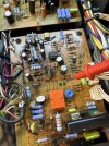
So where I have the high dc v on the left amp board how can I bring that to normal I have tested every transistor in the board they all are working. I changed the caps but still have 347v dc. At that two prong tp on the amp board.
M
Mark.Cass
I also checked the 4 bias diodes and they seem fine but I have not replaced them should I twist two 4148’s together and replace the four of them with 8 4148’s anyway.
M
Mark.Cass
Hey ray just a update so I was able to get the 13mv on both sides and I checked all the output transistors to make sure none were burnt they are all perfect but I still can’t get it out of protection. I’m so frustrated. lol.
Ray Gianelli
Ray Gianelli
Mark, I can't help you if you won't do what I ask.

So, one more time. Black DMM probe to ground, red probe to one of the bias test points. Doesn't matter which. Do this for both channels. Tell me what you get.
M
Mark.Cass
so I’m not sure which one is the test point for bias but the one on the board reads 344mv and the one on the heat sink reads 22.4 mv right ch. left ch on amp board tp 2.1mv one on heat sink 29mv I apologize im really trying.

Attachments

  • image.jpg
    image.jpg
    175.2 KB · Views: 3
  • image.jpg
    image.jpg
    130.6 KB · Views: 3
Ray Gianelli
Ray Gianelli
I apologize. But I'm confused, because the message you sent that's time stamped 8:28 PM says that you were able to get 13mV on both sides, so I assumed you knew where the bias test points were. They're on the output board for each channel.
M
Mark.Cass
Ok then yes the bias is not a problem the problem exists that it won’t come out of protection I got confused cuz right next to the bias adjustment pot there are two test pins l thought that was where you tested. Now on that pin one side has just about zero mv the other side has 344mv. The bias is fine.
M
Mark.Cass
I was nervous cuz of the high mv on the left side amp board thinking that was bias I’m really sorry for my bad descriptions. If pics would help let me no
Ray Gianelli
Ray Gianelli
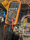
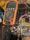
OK, IIRC there are 3 test points on each output board. You measure bias between Vct and Iid. the other pin is ground. Measure either of these 2 to the chassis. The test point marked E is also ground, and will yield zero volts.

You need to determine if there is significant DC voltage on one of the output stages that is keeping the amp in protection.
M
M
Mark.Cass
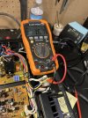
This is right ch first one is vct to ground. Second is lld to ground

Attachments

  • image.jpg
    image.jpg
    129.1 KB · Views: 4
  • image.jpg
    image.jpg
    132.3 KB · Views: 4
M
Mark.Cass
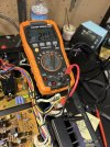
First is lld to ground second is vct to ground

Attachments

  • image.jpg
    image.jpg
    144.7 KB · Views: 5
  • image.jpg
    image.jpg
    144.8 KB · Views: 5
M
Mark.Cass
Should I measure between lld and vct
Ray Gianelli
Ray Gianelli
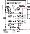
You measure between Iid and Vct to set bias. You're not doing that, you're trying to see if there's offset, and there sure is. Looks like the servo isn't working. Check the servo DC power supplies:

1710982157131.png
M
Mark.Cass
thank you q120. -0.536v at e and 0.2mv b q 121 has -22v at b and e definitely not right.
Ray Gianelli
Ray Gianelli
Q121 is fine, I checked my notes and the voltages should be around +/-21 volts. A couple of volts isn't an issue.
The issue is with Q120. -.536 volts where you should have +21 is a big red flag.
Back
Top Bottom