• The move to the new server is done. There are some software and database maintenance updates in process. This has us passing the hat around to help out. We appreciate any donations. Seriously, even a dollar helps. The payment page may be found here - https://www.audiokarma.org/support.html

Kenwood KA-4006 "new to me" not working

Status
Not open for further replies.

roger2

.
Subscriber
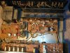
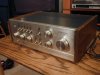
New to me Kenwood KA-4006. $16 from eBay and local pick-up so it did not get bounced around in shipping.

Was advertised as, "Can not get this to power up" and "I'm no expert". Dirty on the outside and very dusty inside. Seems like a pretty solid little amp. I like it :yes:

I was, of course, hoping for a blown internal fuse. Yes it was there. Now I am hoping for no further complications :worried:

Everything inside looks original including the fuses. That's a hopeful sign I think. So I am going to blow out the dust and hook it up to my poor-man's-variac and see what happens.

I would like to bring this forgotten Kenny back to life if possible...
 

Attachments
  • DSCN0022.JPG
    DSCN0022.JPG
    128.2 KB · Views: 393
  • DSCN0001.JPG
    DSCN0001.JPG
    72.5 KB · Views: 305
  • DSCN0002.JPG
    DSCN0002.JPG
    66.8 KB · Views: 260
  • DSCN0003.JPG
    DSCN0003.JPG
    136.3 KB · Views: 274
  • DSCN0005.JPG
    DSCN0005.JPG
    131.6 KB · Views: 262
Last edited:
Register to hide this ad
Great buy. :thmbsp: It looks like it will be a very nice unit once you get it cleaned and back in operating mode.
 
Amp cleaned up pretty nice for a first pass. I will do a more thorough cleaning later but for now it looks decent.

But there are issues with this amp. I need to ask for some troubleshooting guidance.

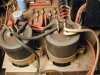
First off, the amp came to me with a blown fuse. See last pic below. Is it possible to tell anything about the cause of the blown fuse by the way it looks?

Next, I replaced the fuse of course. But did not want to plug into full 120V AC. So I used a dim-bulb variac and fed the amp about 40V AC. Controls zeroed out, no inputs, speaker switch set to "Off".

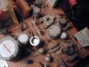
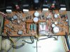
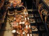
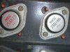
Under these conditions I felt heat coming from the left side of the board shown in pic 3 below. After removing power I touched each component until I found the source of the heat - the two emitter resistors on the left side were extremely hot to the touch. Nothing else was hot. The two output TO-3's corresponding to the hot emitters were possibly only slightly warmer than their counterparts on the other side.

Next, after everything cooled down, I hooked up a meter to one of the emitter resistors and found .935V across it. That is again with only 40V AC feeding the amp. .935 Volts, not milivolts. Turning the bias adjustment variable resistor had no effect on the reading value.

And that is what I know. Can anyone make a deduction based on this information?

Thanks in advance...
 

Attachments

  • DSCN0007.JPG
    DSCN0007.JPG
    112.1 KB · Views: 155
  • DSCN0001.JPG
    DSCN0001.JPG
    70.6 KB · Views: 234
  • DSCN0004.JPG
    DSCN0004.JPG
    71 KB · Views: 221
  • DSCN0008.JPG
    DSCN0008.JPG
    59.1 KB · Views: 162
Last edited:
Blown outputs and most likely other collateral damage.

Would "blown" mean shorted or open?

OK, I am an electronics novice. But it seems that, even with a blown output, turning the bias adjustment variable resistor should have at least some effect on the reading I see when measuring voltage across the emitter. Am I wrong, if so why?


Is it conceivable that the bias adjustment resistor itself is shorted?
 
There is a good schematic for the KA-4006 here:

http://www.fotoalbumet.com/homepage...0cac7d10460e296e21ef7c88&intDesign=1&intEdit=

One of the power transistor is probably shorted on the hot channel. Turning the bias adjustment will have no effect if the power transistors are shorted.

Remove the power transistors on the defective channel and test them. With power transistors removed, see if you have 0V DC (reference to ground) at the emitter resistors. If you have 0V, you can test your amp with headphones (NO speaker). Do you have good sound from both channels on the phones?
 
ecluser,

Thanks for weighing in on this.

I snagged that schematic about a week back when you posted it for another AK'er. But I can not get it to open on my PC. It consists of two .png files both large - 3.8 MB and 2.8 MB. I have a well regarded image viewer, FineView, that is supposed to handle .png files. But when I try it freezes up my computer.

If I can not get this schematic to work I would have no problem buying the full service manual.

But depending upon the complexity of this project I may choose to put this amp in the project que. Although I have been learning a lot observing on AK, I have yet to put soldering iron to PCB. Getting close to doing my first recap and/or repair project. But when the time comes I want to begin with something fairly simple.

So I guess my goal now is to assess the potential complexity of this project.

When you say "power transistor" I assume you are referring to the output TO-3's, correct?

If so, are those still obtainable? How much collateral damage might there be?
 
OK, thank you ecluser

I guess I would be a fool NOT to proceed. Even though this is probably way more than I had anticipated for a "first" project.

It may take a week or two for me to get up to speed. I will either find a way to read that schematic or will get a full SM. I also need to get a decent soldering iron and practice on a junk PCB.

Will post again when I have completed the steps from your previous post.


One more question for now though:

If it is necessary to substitute new TO3's for a blown pair, wouldn't the other pair need replaced to match the new ones?
 

Attachments

  • DSCN0010.JPG
    DSCN0010.JPG
    136.7 KB · Views: 117
Good idea to practice on junk boards.

You don't need to replace both pairs but when you consider the minimum order and delivery costs, changing both pairs is not much more expensive.
 
Yes, the .pdf's are much more user friendly. I can manipulate those with no problems.

I did get the .png's working too. The generic Windows Picture and Fax Viewer will open them on my PC, but is cumbersome. Even though those files are 3.8MB and 2.8MB it requires 400-700MB of memory to open them (I have only 512MB Ram). That is what was causing my machine to hang. I changed my page file settings from a fixed 768MB to "system managed" and that helped a little.

My plan is to take the .png's to my local print shop and have some very large (@30" wide) hard copy prints made. And the .pdf's will be very handy for zooming in on stuff on my computer monitor.

So documentation is well covered I think. Thank you very much ecluser :thmbsp: I will post back when the TO3's are out and tested.
 
...........Remove the power transistors on the defective channel and test them. With power transistors removed, see if you have 0V DC (reference to ground) at the emitter resistors. If you have 0V, you can test your amp with headphones (NO speaker). Do you have good sound from both channels on the phones?

1) Power transistors removed and tested as per this thread (EchoWars):
http://www.audiokarma.org/forums/showthread.php?t=43186

Q22 and Q24 (left side) both test bad. The other two, Q21 and Q23, test good.


2) No DC voltage present on any of the emitter legs


3) Good sound from headphones both channels except for some crackle when turning the balance knob (will Deoxit that later when front-end is taken apart to recap).


What's next?


EDIT: the main board in this KA-4006 is either X07-1350-10, as shown on the second of the .png schematics, or X07-1350-12 (not shown). The differences in these two boards is small, only 4 components (Ce28, Re3, Re4, De8).
 
Last edited:
Since you have good sound on phones and no DC voltage, it's time to install new power transistors. But before installing the power transistors, I suggest that you reduce the bias to minimum. Measure the DC voltage drop in the 330 Ohms resistor (one X07-1280-12 board this is Re38, and on X07-1350-10 board this is Re42) and turn the bias trim pot for the minimum voltage. Once the power transistors are installed you will need to readjust the bias for the correct value.

The bias current recommended by Kenwood for this amp (see part 3 on this link) is 30mA. This translates to 28mV between the emitters of the power transistors (30mA X (2 X 0.47 Ohm) = 28 mV)

http://www.fotoalbumet.com/homepage...0cac7d10460e296e21ef7c88&intDesign=1&intEdit=
 
Last edited:
one thing you could do would be reinstall the two good transistors on the good side, leave the bad ones out, and continue up on the voltage with the variac slowly, and see if the good channel works.

I worked on a similar kenwood years ago for a friend, threw a pair of 2n3055's in the bad channel (and some cooked emitter resistors) and it worked fine, but ymmv.

Next step would be to look for the availability of the output transistors, or see if there is a good sub listed for it.
 
There is no voltage on the schematic but from the secondary voltage of the transformer we can deduce that the DC supply voltages on the power amp board are close to ±34V. It is not 100% safe to use a pair of 2N3055/2N2955 on this amp since their breakdown voltage (Vceo) is 60V. A little larger with the 330 Ohms base resistors, possibly ~65V.
 
Thanks guys I appreciate your assistance. ecluser is dead-on about the supply voltages... 34v measured across the main supply caps. Its not like I have a spare pair of 2N3055/2N2955's sitting around anyway, lol, this is my first amp project, no spare parts of any kind. :D

And ecluser the main board in this amp is definitely NOT the X07-1280-12 so it will not be necessary to refer to its part numbers. It says right on the board "X07-1350-10" however, I suspect it may actually be the X07-1350-12 because Re3,4 is 2.2K as shown in the parts list with a Remark "-12". In any case the schematic from the 2nd .png (the revised one) is the one that shows the main board in my amp.

----------------------------------------------------------------------------------------------------------------
The output transistors are 2sa627 and 2sd188

I entered those numbers into the search text box at Mouser, DigiKey, MCM, OnSemi, Fairchild and B&D Enterprises with no luck. Still, I would prefer to stay with the original parts if at all possible.

Question 1: Where else can I look for a seller that might possibly have 2sa627 and/or 2sd188?


RE Substitutes:
Fairchild listed FJA6810 as a sub for 2sd188 (out of stock)
MCM listed 2sa747 as a sub for 2sa627 @ $9.19
B&D listed MJ15015G as sub for 2sd188 @$2.55
B&D listed MJ15016G as a sub for 2sa627 @ $2.89

Seems like a no brainer but I have to ask...

Question 2: Can I trust B&D's cross reference? Are the B&D substitutes good replacements for my 2sa627 and 2sd188 outputs?


Question 3: Is B&D Enterprises a reputable company to order from? Any other AK'ers use them?


.
 
Last edited:
Status
Not open for further replies.
Back
Top Bottom