

You are using an out of date browser. It may not display this or other websites correctly.
You should upgrade or use an alternative browser.
You should upgrade or use an alternative browser.
Kenwood KA-4006 "new to me" not working
- Thread starter roger2
- Start date
- Status
- Not open for further replies.


Thank you so much Oilmaster for all of the additional documentation for the KA-4006 :thmbsp:
Apologies to all of you who have been so generous in helping me with this project for the very long delay since my last post here.
I have been troubleshooting the relay timing issues as discussed in the last few posts. Will report my findings shortly.
Apologies to all of you who have been so generous in helping me with this project for the very long delay since my last post here.
I have been troubleshooting the relay timing issues as discussed in the last few posts. Will report my findings shortly.
getting clear on the schematics
As there has already been some confusion relating to schematics (and it has been almost a year since this thread has been active) I thought I would try to get it all clear before proceeding further
The KA-4006, as well as its sister receivers KR-4400 and KR5400, were all revised at some point to implement an improved DC Voltage Protection Circuit. This revision required changes to the main amp boards of these three units. The KA-4006 under discussion in this thread is the revised version with the new main amp board and new protection circuit.
post #13, page 1 - ecluser provided a link to a site with the full schematics in pdf form. This site has 2 pages of schematics. The first page has the full schematic including all boards and the old main amp board. The second page has the schematic and parts list for the revised main amp board.
post #100, page 5 - Oilmaster provided the Sevice Bulletin pertaining to the new protection circuit. It contains a schematic that is correct as far as the electronics go, but the component numbering is "generic" and does not match what is on the actual schematic for the new protection circuit. Also, note that the drawing in this post is flip-flopped top-to-bottom when compared to the full schematic. Of particular interest are the 6 numbered points describing circuit operation.
post #101, this page - Oilmaster further posted an SM Supplement which is very similar (though not identical) to the page 2 (new main amp board) schematic from the link on post #13. The schematic linked to via post #13 shows the board voltages that have apparently been blacked-out on the schematic in post #101.
One further note regarding voltages: some components in the new main amp board of KA-4006 have been further revised vs the new boards for the KR-5400 and KR-4400. Relevant here is that for DE-8 Kenwood used an 11v zener in my amp, not 14v as shown on the schematic. This info can be found in the parts list.
Another big thank you to ecluser and Oilmaster for the excellent documentation :thmbsp:
As there has already been some confusion relating to schematics (and it has been almost a year since this thread has been active) I thought I would try to get it all clear before proceeding further
The KA-4006, as well as its sister receivers KR-4400 and KR5400, were all revised at some point to implement an improved DC Voltage Protection Circuit. This revision required changes to the main amp boards of these three units. The KA-4006 under discussion in this thread is the revised version with the new main amp board and new protection circuit.
post #13, page 1 - ecluser provided a link to a site with the full schematics in pdf form. This site has 2 pages of schematics. The first page has the full schematic including all boards and the old main amp board. The second page has the schematic and parts list for the revised main amp board.
post #100, page 5 - Oilmaster provided the Sevice Bulletin pertaining to the new protection circuit. It contains a schematic that is correct as far as the electronics go, but the component numbering is "generic" and does not match what is on the actual schematic for the new protection circuit. Also, note that the drawing in this post is flip-flopped top-to-bottom when compared to the full schematic. Of particular interest are the 6 numbered points describing circuit operation.
post #101, this page - Oilmaster further posted an SM Supplement which is very similar (though not identical) to the page 2 (new main amp board) schematic from the link on post #13. The schematic linked to via post #13 shows the board voltages that have apparently been blacked-out on the schematic in post #101.
One further note regarding voltages: some components in the new main amp board of KA-4006 have been further revised vs the new boards for the KR-5400 and KR-4400. Relevant here is that for DE-8 Kenwood used an 11v zener in my amp, not 14v as shown on the schematic. This info can be found in the parts list.
Another big thank you to ecluser and Oilmaster for the excellent documentation :thmbsp:
Last edited:
troubleshooting relay timing and turn on/off thump as described in post #97
Before I list the troubleshooting steps completed I need to note that the turn on/off thump had all but disappeared before I did anything listed below. Even with volume up there is only a barely audible blip, not enough to even call it a thump, at power up. I can only assume that replacing the old tone board (preamp) opamp had something to do with this development (tone board thread)
The "backwards" relay on/off timing has not changed however. The speaker protection relay closes approximately one second after the amp is powered on and opens about three seconds after the amp is powered down. Fixing this timing issue was the goal. Did not happen, but here is what I tried (schematic attached below):
1) verified orientation of all new caps and transistors (all electrolytics as well as Qe25 and Qe26 are new)
2) replaced De6 and De7, formerly 1S2076, with new IN4148s
3) tested resistor Re57 out of circuit and all other relevant resistors in circuit (not accurate readings, but none were shorted or over nominal rating)
4) re-replaced capacitor Ce26. It was originally one of those orange "low leakage" caps which I had replaced with a Panasonic FM. Now I have put in a low leakage Nichicon KL
5) checked all solder joints in relevant circuits. found no issues but went ahead and reflowed a few of them just to be sure
6) verified that Pin 10 on the schematic is blank on the board - just an empty hole
7) finally, as suggested above by Oilmaster, I (temporarily) reversed the modification to the relay circuit (see posts 49-59)
Long story short, none of these changes fixed the relay timing issue. However, I have two observations to report:
First, when I did reverse the relay mod there was a slight change in the behavior of the relay: when powering down the amp the relay opened in about two seconds instead of three. But the relay still closed very quickly upon power up. So the relay mod is not causing the wacky timing issue. I put the mod back the way it was, with resistor in place of De8 and a (fly-wheel) diode across the relay coil, to protect the relay.
Secondly, and this seems odd to me so maybe it is a clue I don't know: when the amp is powered up there is .339vdc across De6 and .339vdc across De7 with black DMM lead on the cathodes. When the red lead is on the cathodes the voltages are -.327 and -.328
Can these diodes have a voltage drop less than their Vf?
Anybody have any other ideas?
.
Before I list the troubleshooting steps completed I need to note that the turn on/off thump had all but disappeared before I did anything listed below. Even with volume up there is only a barely audible blip, not enough to even call it a thump, at power up. I can only assume that replacing the old tone board (preamp) opamp had something to do with this development (tone board thread)
The "backwards" relay on/off timing has not changed however. The speaker protection relay closes approximately one second after the amp is powered on and opens about three seconds after the amp is powered down. Fixing this timing issue was the goal. Did not happen, but here is what I tried (schematic attached below):
1) verified orientation of all new caps and transistors (all electrolytics as well as Qe25 and Qe26 are new)
2) replaced De6 and De7, formerly 1S2076, with new IN4148s
3) tested resistor Re57 out of circuit and all other relevant resistors in circuit (not accurate readings, but none were shorted or over nominal rating)
4) re-replaced capacitor Ce26. It was originally one of those orange "low leakage" caps which I had replaced with a Panasonic FM. Now I have put in a low leakage Nichicon KL
5) checked all solder joints in relevant circuits. found no issues but went ahead and reflowed a few of them just to be sure
6) verified that Pin 10 on the schematic is blank on the board - just an empty hole
7) finally, as suggested above by Oilmaster, I (temporarily) reversed the modification to the relay circuit (see posts 49-59)
Long story short, none of these changes fixed the relay timing issue. However, I have two observations to report:
First, when I did reverse the relay mod there was a slight change in the behavior of the relay: when powering down the amp the relay opened in about two seconds instead of three. But the relay still closed very quickly upon power up. So the relay mod is not causing the wacky timing issue. I put the mod back the way it was, with resistor in place of De8 and a (fly-wheel) diode across the relay coil, to protect the relay.
Secondly, and this seems odd to me so maybe it is a clue I don't know: when the amp is powered up there is .339vdc across De6 and .339vdc across De7 with black DMM lead on the cathodes. When the red lead is on the cathodes the voltages are -.327 and -.328
Can these diodes have a voltage drop less than their Vf?
Anybody have any other ideas?
.
Attachments

Last edited:
One further attempt to resolve the relay on/off timing issues described above...
After reading this post by ecluser in another thread I decided to verfiy, again, the orientation of Qe26 that controls the relay. I have already checked this visually several times. This time I checked each leg of the transistor with a DMM confirming that each is connected to the correct component per the schematic.
As much as I don't like to leave this in an imperfect state, I do not know what else to do.
However, there has been a change in the turn on/off behavior I described in post 97. After re-working the tone/pre-amp board (next post) the thump is all but gone. In fact, even though the relay timing is still not right, turn on/off is very well behaved now. Nothing at turn on and only a very slight "bump" at turn off. Even when volume control is up.
As I learn more about circuits perhaps I will come back and look at this again sometime. But as of now it is not causing any real problems.
After reading this post by ecluser in another thread I decided to verfiy, again, the orientation of Qe26 that controls the relay. I have already checked this visually several times. This time I checked each leg of the transistor with a DMM confirming that each is connected to the correct component per the schematic.
As much as I don't like to leave this in an imperfect state, I do not know what else to do.
However, there has been a change in the turn on/off behavior I described in post 97. After re-working the tone/pre-amp board (next post) the thump is all but gone. In fact, even though the relay timing is still not right, turn on/off is very well behaved now. Nothing at turn on and only a very slight "bump" at turn off. Even when volume control is up.
As I learn more about circuits perhaps I will come back and look at this again sometime. But as of now it is not causing any real problems.
Last edited:
tone/pre-amp board
I had originally intended to simply replace the electrolytic caps on the tone board. But this board became a project in and of itself as I learned a few things:
- the tone circuit also serves as pre-amp
- this board has 3 electrolytics (per channel) that are in the signal path
- this board uses an early and not well regarded 4558 opamp
- the opamp mounting uses a non-standard hole spacing
I started another thread which, unintentionally, became the place where most of the work done on the tone board was discussed:
Can I increase capacitance on these TONE BOARD caps? A very interesting and informative thread where much of what is described below was discussed and/or debated by some of AK's most awesome contributors.
Work done on the tone board includes:
- modified a standard DIP opamp socket to fit
- installed OPA2134 opamp to replace JRC4558
- eliminated bipolar electrolytics Ci5,Ci6 (output) as the new opamp had low enough DC offset (per EchoWars). The vacant positions were jumpered.
- replaced electrolytics Ci1, Ci2 (input) with Wima film
- replaced electrolytics Ci3, Ci4 with Elna Silmic II (@ 10 uF these are too large to replace with film)
- replaced electrolytics Ci15, Ci16 (decoupling) with Panasonic FM and bypassed these with .22uF Panasonic ECQ-V film (soldered to underside of board)
The sum of all these changes made a noticeable improvement in the sound of the amp. As access to tone board was difficult I did not have the luxury of evaluating these changes individually.
As it stands now there is only one electrolytic (Elna Silmic II) remaining in the signal path in this amplifier. As one on the tone board was eliminated and another on the tone board was replaced with film. Also the input caps to the main amp board have been changed from tantalum to polypropylene.
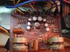
Before and after pics...
I had originally intended to simply replace the electrolytic caps on the tone board. But this board became a project in and of itself as I learned a few things:
- the tone circuit also serves as pre-amp
- this board has 3 electrolytics (per channel) that are in the signal path
- this board uses an early and not well regarded 4558 opamp
- the opamp mounting uses a non-standard hole spacing
I started another thread which, unintentionally, became the place where most of the work done on the tone board was discussed:
Can I increase capacitance on these TONE BOARD caps? A very interesting and informative thread where much of what is described below was discussed and/or debated by some of AK's most awesome contributors.
Work done on the tone board includes:
- modified a standard DIP opamp socket to fit
- installed OPA2134 opamp to replace JRC4558
- eliminated bipolar electrolytics Ci5,Ci6 (output) as the new opamp had low enough DC offset (per EchoWars). The vacant positions were jumpered.
- replaced electrolytics Ci1, Ci2 (input) with Wima film
- replaced electrolytics Ci3, Ci4 with Elna Silmic II (@ 10 uF these are too large to replace with film)
- replaced electrolytics Ci15, Ci16 (decoupling) with Panasonic FM and bypassed these with .22uF Panasonic ECQ-V film (soldered to underside of board)
The sum of all these changes made a noticeable improvement in the sound of the amp. As access to tone board was difficult I did not have the luxury of evaluating these changes individually.
As it stands now there is only one electrolytic (Elna Silmic II) remaining in the signal path in this amplifier. As one on the tone board was eliminated and another on the tone board was replaced with film. Also the input caps to the main amp board have been changed from tantalum to polypropylene.
Before and after pics...
Attachments

Last edited:
4 Channel Normal/Separate
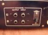
These two pair of RCA jacks are not the same as typical pre-in/main-out jacks. This interface was originally intended to allow for a 4-channel set-up. A separate amplifier as well as a decoder or demodulator would have been necessary to run in 4-channel mode (from the Owners Manual).
When this switch is in the "Separate" position, the associated RCA jacks provide an insert point into the circuitry. The 4-Channel inputs bypass the input selector switch and the tape dubbing/monitor switches, and connect directly to the board with the Mode/Muting/Tone/Filter switches which are part of the tone/pre-amp section.
In other words, when the 4 Channel switch is set to "Separate" and a source connected to the 4-Channel input jacks, all the tone controls and the volume control are still functional. I have been using the amp this way to eliminate the input selector and tape-related switches from the path of the input signal. I am using a CD player as my sole source. This would of course not work for phono inputs or if more than one source was required.
When the switch is set to "Separate" anything connected to the normal input jacks is accessible only via the 4-Channel RCA Outputs and the input selector switch functions to choose among inputs.
In addition to the way I am using this 4-Channel circuitry, it would also be an ideal place to insert something, an EQ, etc., or could be used for troubleshooting to isolate groups of controls.
These two pair of RCA jacks are not the same as typical pre-in/main-out jacks. This interface was originally intended to allow for a 4-channel set-up. A separate amplifier as well as a decoder or demodulator would have been necessary to run in 4-channel mode (from the Owners Manual).
When this switch is in the "Separate" position, the associated RCA jacks provide an insert point into the circuitry. The 4-Channel inputs bypass the input selector switch and the tape dubbing/monitor switches, and connect directly to the board with the Mode/Muting/Tone/Filter switches which are part of the tone/pre-amp section.
In other words, when the 4 Channel switch is set to "Separate" and a source connected to the 4-Channel input jacks, all the tone controls and the volume control are still functional. I have been using the amp this way to eliminate the input selector and tape-related switches from the path of the input signal. I am using a CD player as my sole source. This would of course not work for phono inputs or if more than one source was required.
When the switch is set to "Separate" anything connected to the normal input jacks is accessible only via the 4-Channel RCA Outputs and the input selector switch functions to choose among inputs.
In addition to the way I am using this 4-Channel circuitry, it would also be an ideal place to insert something, an EQ, etc., or could be used for troubleshooting to isolate groups of controls.
Attachments
Last edited:
power supply
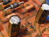
new parts in the 14v regulated supply serving phono and pre-amp boards:
- 1%, 2watt Vishay Dale metal film resistors
- 2% 14v zeners
- 25v/680uF Panasonic FM replaces 16v/470uF
new parts in the main PS:
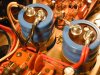
- original main caps were 6,800uf which, for a 34 watt amp, is pretty good size already. Of course I could not resist beefing up to 10,000uF
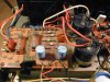
- original rectifiers were 2.5 amp. These were replaced with UF5402 at 3 amp. But the main reason I upgraded the rectifiers was to obtain greater ability to handle inrush current of the larger main caps. Ifsm of the original rectifiers was 100A, Ifsm of the UF5402 is 150A
In addition, the UF5400 series is "Soft Recovery UltraFast". Whether this matters is the subject of intense and, as far as I know, unresolved debate (have read through some DIYAudio threads dozens of pages long).
This power supply refresh/upgrade has made a nice improvement in the sound of the amp. Bass notes have really cleared up. And I don't know if it is possible, but it seems the high end is cleaner and more extended.
EDIT 2017: Five years later my feeling is that upsizing the main filter caps to 10k uF was unnecessary. As for physical size and mounting issues, I don't recall what, if any, options would have been available at a smaller uF.
new parts in the 14v regulated supply serving phono and pre-amp boards:
- 1%, 2watt Vishay Dale metal film resistors
- 2% 14v zeners
- 25v/680uF Panasonic FM replaces 16v/470uF
new parts in the main PS:
- original main caps were 6,800uf which, for a 34 watt amp, is pretty good size already. Of course I could not resist beefing up to 10,000uF
- original rectifiers were 2.5 amp. These were replaced with UF5402 at 3 amp. But the main reason I upgraded the rectifiers was to obtain greater ability to handle inrush current of the larger main caps. Ifsm of the original rectifiers was 100A, Ifsm of the UF5402 is 150A
In addition, the UF5400 series is "Soft Recovery UltraFast". Whether this matters is the subject of intense and, as far as I know, unresolved debate (have read through some DIYAudio threads dozens of pages long).
This power supply refresh/upgrade has made a nice improvement in the sound of the amp. Bass notes have really cleared up. And I don't know if it is possible, but it seems the high end is cleaner and more extended.
EDIT 2017: Five years later my feeling is that upsizing the main filter caps to 10k uF was unnecessary. As for physical size and mounting issues, I don't recall what, if any, options would have been available at a smaller uF.
Attachments

Last edited:
project completed!
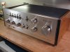
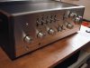
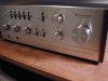
When I started this thread I had never soldered on a PCB.... a mere 2 1/2 years and few starts-and-stops later, my first rebuild/refresh project is closed up and making music
Sounding fresh, tight and clear.
Huge thanks to the generous AK'ers who have assisted with my first major amplifier project, in particular...
ecluser: who, for starters, not only procured the Service Manual for me, but when I was unable to handle a .png file format, ecluser converted it to .pdf and handed me the link. He then proceeded to guide me through diagnosing and repairing the blown outputs and assisted in key areas throughout. Your help and your expertise appreciated more than you know :thmbsp:
EchoWars: who seemed never to be far away. Amazingly, there are probably hundreds of AK'ers who feel the same way I do as EW keeps giving us what is needed to keep a myriad of projects moving forward. And has anyone mentioned recently the treasure of threads/posts that EchoWars has left behind for reference here at AK? I wish that more people would just take the time to search a little instead of asking the same questions over and over.
Oilmaster: who, via PM's, showed infinite patience addressing my various noob questions in detail, and encouraged me to carry on.
When I started this thread I had never soldered on a PCB.... a mere 2 1/2 years and few starts-and-stops later, my first rebuild/refresh project is closed up and making music
Sounding fresh, tight and clear.
Huge thanks to the generous AK'ers who have assisted with my first major amplifier project, in particular...
ecluser: who, for starters, not only procured the Service Manual for me, but when I was unable to handle a .png file format, ecluser converted it to .pdf and handed me the link. He then proceeded to guide me through diagnosing and repairing the blown outputs and assisted in key areas throughout. Your help and your expertise appreciated more than you know :thmbsp:
EchoWars: who seemed never to be far away. Amazingly, there are probably hundreds of AK'ers who feel the same way I do as EW keeps giving us what is needed to keep a myriad of projects moving forward. And has anyone mentioned recently the treasure of threads/posts that EchoWars has left behind for reference here at AK? I wish that more people would just take the time to search a little instead of asking the same questions over and over.
Oilmaster: who, via PM's, showed infinite patience addressing my various noob questions in detail, and encouraged me to carry on.
Attachments
Last edited:

- Status
- Not open for further replies.