• The move to the new server is done. There are some software and database maintenance updates in process. This has us passing the hat around to help out. We appreciate any donations. Seriously, even a dollar helps. The payment page may be found here - https://www.audiokarma.org/support.html

Magnavox 142 - rebuild/modification thread

I would like your opinions too.

OK. You still need to compute the correct dropping resistor for the 0D3s. I don't have any real data to go off of so I'll use the tube manual data for 6V6s at 285v plate and screen and assume the 5Y3s drop 60v which should be in the ballpark.

Supply voltage= 315+60= 375v
Max screen draw per pair= 13.5 ma
Idle screen draw per pair= 4 ma

[(13.5-4)/2]+4 = 8.75 ma draw per pair = 17.5 ma per quad

Using the formula I posted earlier: (375-300)/(.02+.0175)= 2000 ohms. The power dissipated will be 75^2/2000 = 2.8 watts so use at least a 5W resistor.
 
One thing to contemplate, running those 12ax7's off the regulated circuit is there
won't be as much filtering there as there would be going through that choke then
larger caps, can't say for sure which way might turn out better, maybe experiment.
(sorry 6SL7 in place of 12AX7)
 
Here is revision 1 of the power supply circuit. This look okay???

Hi Mark that looks fine .

You can sub the small chokes in place of the 10 ohm resistors for beter ripple rejection , if you want to regulate the B+ to the 6SL7 that you going to use in place the 12AX7 i would add another 6V6 as a regulator tube . Use the voltage from the OD3 to the grid of the 6V6 and the plate voltage from the highly filtered supply .That will give you the best of both supplies. If you go off the OD3's the 6SL7's woun't have any time delay for its B+ and alot more capacitance will be needed on the regulated line .

All sugestion welcome as far as i'm concerned .
 
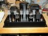
Here is the layout so far. I havr completely striped the chassis and cleaned it. Trannies still need cleaned, and obviously some paint on all of it too.

I like that idea of one more 6v6 - that spot in the center can be punched out and the 6v6 added.

Any thoughts? Any suggestions for a color scheme. Right now I am thinking an olive chassis and end bells, the bodies of the tranies satin black. All hardware black. Then wrap the whole unit in some wood.
 

Attachments

  • P1010033.jpg
    P1010033.jpg
    86.5 KB · Views: 210
Question.
I want to up the capacitance from 40 to 50uf on the first cap, I also want to up the capacitance on the last cap of the regulated supply, up it from 20 to 100. Will this work? If I do this, it simplifies what I have to order and what I have to mount on the chassis.

Thanks,
Mark

BTW - I REALLY APPRECIATE ALL THE HELP ON THIS!!!
 
If you go off the OD3's the 6SL7's woun't have any time delay for its B+ and alot more capacitance will be needed on the regulated line.

I would think that a combined 170uf of capacitance plus the extra 20uf after the 100k resistor would be enough. It's more capacitance than virtually any amp I have around here. I must be missing something here.
 
according to the sams photofact, the output is a 4.3ohm. The output tranny has a 3.7k impedance. Interestingly enough, the output has two output taps. one was for an auxillary speaker. It is not labled as to what output impedance should be used.

ANyone here know? Anyone here know how to measure it?

I measured one of those transformers with a signal generator. Looks like the aux tap was about a 2 ohm tap. Would make sense... that would make the aux speaker a little less loud than the main. Or, if you wanted to wire BOTH the main and aux speaker to one tap... it would work.

Regards,
Gordon.
 
I measured one of those transformers with a signal generator. Looks like the aux tap was about a 2 ohm tap. Would make sense... that would make the aux speaker a little less loud than the main. Or, if you wanted to wire BOTH the main and aux speaker to one tap... it would work.

Regards,
Gordon.

He yGordon,
Thanks! I'll do that. ANy opinion about running this amp with an 8 ohm speaker load?
 
Update,
I have aquired a set of Edcor 100watt 4.2k impedance output transformerss that have 4/8/16 output taps.
http://www.edcorusa.com/products/458-cxpp100-ms-4_2k.aspx

These are going to replcae the original OPT with a 4.3output tap. This is a substancial improvement in the iron I think.

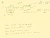
I am also going to add a VU meter to each. Attached is a schematic of how I think it should work. Any ideas or opinions on the schematic?

Alos attached is a pic of the meter.

Heck, this thing is barely a 142 anymore. Probably should have started from scratch on this.

Oh well.
 

Attachments

  • meter2.jpg
    meter2.jpg
    33.6 KB · Views: 94
  • P1010035.jpg
    P1010035.jpg
    54.9 KB · Views: 89
Just got some info from another aker.
The diodes in the meter schematic above are incorectly placed. Both of the diodes that are currently in series, should be paralleled with the meter. I'll redraw and repost shortly.
 
Last edited:
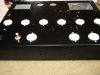
here some pics of the chassis after it has been cleaned up and painted. I think the resistors/caps/etc will be hear in the next few days. I'll work on the wrap until they get here. Hoefully, I'll have the amp done by the end of next week.

BTW - the OPT is just to hide the hole. It'll be replaced with an edcor.
 

Attachments

  • P1010021.jpg
    P1010021.jpg
    91.3 KB · Views: 176
  • P1010025.jpg
    P1010025.jpg
    85.5 KB · Views: 150
I am going to paint them to match. I am trying to get a deep black look. My plan for the wraps is a cedar with some abalone inlay. .
We'll see how that works.
 
The vu meters shown have an outside dimension of 2x2 inches. The actual meter is about 1x1.75. On the top of the deck, right in the center is where I plan on putting them. I am going to build a bezel that tilts the meter slightly forward. This will also cover the one place where there is a plug that didn't get punched out.


Make sense?
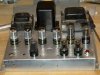
 
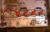
I made some progress today. I still have a long way to go.
Pics below of the progress.
I am waiting for the caps/resistors/etc. to finish this up. Probably get the rest of the stuff either monday or tuesday.
 

Attachments

  • nov15.jpg
    nov15.jpg
    65.9 KB · Views: 141
  • P1010036.jpg
    P1010036.jpg
    95.3 KB · Views: 166
The vu meters shown have an outside dimension of 2x2 inches. The actual meter is about 1x1.75. On the top of the deck, right in the center is where I plan on putting them. I am going to build a bezel that tilts the meter slightly forward. This will also cover the one place where there is a plug that didn't get punched out.


Make sense?
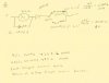
Yep!

Are you using #6-32 hardware to mount everything? I know there used to be rivets in there.

BTW, ... looks good.
 
Back
Top Bottom