• The move to the new server is done. There are some software and database maintenance updates in process. This has us passing the hat around to help out. We appreciate any donations. Seriously, even a dollar helps. The payment page may be found here - https://www.audiokarma.org/support.html

Magnavox 142 - rebuild/modification thread

6-32 works in the holes, but the sockets have this mounting ring wich doesn't allow 6-32. I went to ace and bout a box of 4-40 stuff. AThe nut fits in the mounting ring perfectly.

The 4-40 still covers the holes well and it looks like it is still plenty solid too.

BTW - thanks for the kind words.
 
I have a 9303 Magnavox which I'm gather parts for a complete rebuild... just like your's.
I plan to strip it down to the bare sheet metal and replace everything save the transformers.

Thanks for the tip on the hardware. Are you using new sockets or reusing the old ones?

BTW, I demand reciprocation of the kind words when I get my rebuild going!! :D
 
I have a 9303 Magnavox which I'm gather parts for a complete rebuild... just like your's.
I plan to strip it down to the bare sheet metal and replace everything save the transformers.

Thanks for the tip on the hardware. Are you using new sockets or reusing the old ones?

BTW, I demand reciprocation of the kind words when I get my rebuild going!! :D

new sockets. I got the ceramic with gold pins. They work well, but considerthe size oft the holes you need to fill before you order them.

Keep us posted on your maggie.
 
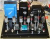
The edcor output trannies arrived today as well as the rest of the caps, resistors, etc. I should be able to finish this in the next few days. The hole on the far left front corner is for the power switch - it hasn't arrived yet. This project is coming along pretty well I think.

Any thoughts on the edcor tranny, paint it satin black to match or leave it blue?

Mark
 

Attachments

  • P1010043.jpg
    P1010043.jpg
    117.8 KB · Views: 158
I like it blue :)
especially since that VU meter in the front is a similar color
you should leave it
maybe find a blue pilot/power light too?
throw your name on the front in blue too like a logo, hehe
but then im partial to blue :p
 
I like it blue :)
especially since that VU meter in the front is a similar color
you should leave it
maybe find a blue pilot/power light too?
throw your name on the front in blue too like a logo, hehe
but then im partial to blue :p

Thanks for the feedback. Getting a blue jewel for the pilot would be easy. If I could match the blue(exactly) I could also paint the endbell on the PS tranny. My plan for the base includes some abalone shell, which also has a nice blue hue. Hmm..........

Thanks again,
Mark
 
Last edited:
Hi Mark ,

Switch the position of the off-on switch an the piolet light , keep the AC all on one side of the amp .

Keep it all black .

It sure looks different than it did here .

With the Edcor output transformers you will be able to use PPP 6V6's , PP 6L6GC's ,EL34's or 6550 with only a change of the cathode resistor
 
Hi Mark ,

Switch the position of the off-on switch an the piolet light , keep the AC all on one side of the amp .

Keep it all black .

It sure looks different than it did here .

With the Edcor output transformers you will be able to use PPP 6V6's , PP 6L6GC's ,EL34's or 6550 with only a change of the cathode resistor

PP? Not PPP 6l6's? Did I understand that correctly?

I was wondering aboiut the ac/dc/ on top of eachother as I ran the wires. Can do on the swap - thanks for the input.
Mark
 
Hi Mark ,

Switch the position of the off-on switch an the piolet light , keep the AC all on one side of the amp .

Keep it all black .

It sure looks different than it did here .

With the Edcor output transformers you will be able to use PPP 6V6's , PP 6L6GC's ,EL34's or 6550 with only a change of the cathode resistor

Hey Mark,
The cathode resistor is the 125 ohm 10 watt resistor correct? Would it be possible to replace that resistor with a series/parallel resistor circuit that also incorporates a potentiometer? Would this work?
 
I plan on trying that out, Dave does well to explain why he does certain things he does.
(And it somewhat reinforces my stand on wanting higher impedance loads on outputs)
 
After stepping back from this and looking at it, I realize this really is no longer a maggie 142. The only original part left is the power supply and the sheet metal chassis. So much for an economy built tube amp.

As such, I am going to start over. I am still going to build the same circuit, but start with a new, slightly larger chassis. This should give me all the room I need to put what I need on the amp. SInce I am going with a new chassis, I might just incorporate two new PS trannies from edcor too. As much as I have spent on this amp, it is likely best to just start with new stuff.

Anyone else ever done this. Gotten close to a goal and realized "oops" should have started from scratch? Then did you start over?
Mark
 
Last edited:
One way to look at it, you'll have TWO amps that way!

Build the all new one, and "rebuild" the old one as well.. :)
 
No. Neither will the 10k. I tried to explain this before, perhaps I was talking french?

edit: hold on, let me add this::D

Hey Scuzzer, I am sure you were not speaking french(or greek), it is who you are talking to that is the problem. Maximus moronus present and accounted for.

I gues I am not sure exactly why the 10k resistor is there. Voltage drop? Current limiting?
 
The VR tubes provide a variable current draw across that resistor to maintain the rated voltage. They have a range of 5ma to 40 ma that they can pull and remain within spec (or lit on the lower end). The combination of the range of current that your screens will pull plus the VR draw is what will lower your voltage to the regulation range due to ohms law across that resistor.

In an earlier post I tried to ballpark the resistor based on expected screen current draw. http://www.audiokarma.org/forums/showpost.php?p=4114464&postcount=22

I haven't played around with VR tubes so I might be wrong though. I'm pretty sure that 10k won't work since the screen draw alone will drop the voltage beyond regulation range.
 
Last edited:
so a 2k 5 watt is what you think is needed? If I were to drop it a little lower, to maybe a 1.5k and 10 watt, the vr tubes would work then, and still bring the regulate the voltage to where it should be for the b+ for the 6v6g tubes - is that correct? This last question I am asking mostly to see if I understand the function here.

THANKS!!!!!!!!!!
 
If I were to drop it a little lower, to maybe a 1.5k and 10 watt, the vr tubes would work then

They should but perhaps not optimally. Optimum is having them around their midpoint of current draw (22.5ma) so they provide the widest positive and negative swing. I was just ballparking the resistor based on tube manual screen current draw. You might find that after you build the amp you need to raise or lower the dropping accordingly. Like always though, if it calls for a 5w resistor a 10w one won't hurt.
 
Back
Top Bottom