

You are using an out of date browser. It may not display this or other websites correctly.
You should upgrade or use an alternative browser.
You should upgrade or use an alternative browser.
Sad Marantz 2600 - Restorable???
- Thread starter skibjr
- Start date

Jailtime
Standin' on a corner
Wow, you do some fine work! It's looking great so far, those heatsink assemblies are flawless. Nice attention to detail, no thermal grease smeared all over the place or anything! Can't wait to hear of the 2600's resurrection!
Well, it's not a receiver, but have you ever replaced the outputs in a Soundcraftsmen MA5002? Absolutely miserable...:bash:
I can conceive of NO receiver being more of a pain-in-the-a$$ to install output transistors in than the Marantz 2500/2600! :yes:
Well, it's not a receiver, but have you ever replaced the outputs in a Soundcraftsmen MA5002? Absolutely miserable...:bash:

skibjr
Super Member
First attempt at power-up...
Got the bridge rectifiers earlier in the week and replaced both of them this afternoon. Lots o' fun - the rectifiers are mounted to the chassis floor under the regulator board, and even after pulling the board, there's still virtually no room to work among all the other circuitry crammed into this box. Finally got it done, did another once-over to verify all my connections, and satisfied myself that there were no obvious issues that would result in my past few months' work going up in smoke.
With a bit of trepidation, I hooked up my dim bulb tester, screwed in a 150W bulb, plugged her in, and hit the power switch.
The fan roared to life (and I mean roared - nothing quiet about it)... and nothing else. No lights, no relay clicks, nothing.
I traced the AC to the 10-ohm, 10W soft-start resistor, which turned out to be wide open. Great - another part to order. Turns out that this particular type of resistor, with the solderable lugs, is unobtanium in this value and wattage, so I'll have to improvise. I suppose I could install a similar resistor with the more common axial leads and just twist/solder the connecting wires together, but that would look crappy. Gotta be a better way - I'll think of something... :scratch2:
I have to wonder what the hell happened to this unit. Whatever it was took out a ten watt resistor, a bridge rectifier, and a whole bank of outputs. Maybe the fan too - perhaps that's why it wasn't included with the receiver. Lightning strike? Massive power surge? I just hope it wasn't the main transformer's primary shorting out. I'm measuring 0.4 ohms across it, and though I don't know what a normal resistance value would be for the primary of a big toroid, this seems a bit lower than I'd expect. All I can do is cross my fingers - I'll be pretty pissed off if after all the work I put in, this thing turns out to be a thousand-dollar doorstop...

westend
Audiopile
Very good thread for restoration, your attention to detail and perserverance is going to pay, methinks. From what you've posted, the receiver must have seen some very high current to take out all of the components you've replaced. Maybe the previous owner crow-barred the outputs while he was looking for another cigar.
I'll be following along on this one, good work and keep the faith!
I'll be following along on this one, good work and keep the faith!

The fan is forced to high speed & all incoming current is forced through the 10 ohm 10W resistor, until the soft-start relay closes. The resistor is usually burnt because the amp blew, took out a fuse, and someone simply replaced the fuse, hoping for the best. But the relay won't close after the fuse replacement because the shorted outputs won't allow the caps to charge enough to generate the voltage needed to do so...therefore the 10 ohm resistor is subjected to many times the wattage it is designed for and opens.
The only oddball thing here is the diode bridge.
I've been replacing the fan and soft-start resistors (on the very few 2500's and 2600's I've worked on) with 25W vitreous enamel power resistors...a 10 ohm for the soft-start, and a 750 ohm (with a piggyback 4.7K 5W) for the fan. There's a pic in post #2 here: http://www.audiokarma.org/forums/showthread.php?t=116273
Huntington Electric from Digikey, #FVT25-10-ND & FVT25-750-ND, plus mounting brackets, #B1003-ND (x2) and the 4.7K 5W resistor (#ALSR5F-4.7K-ND) to bring the effective resistance to the fan down to about 650 ohms (stock resistor is 680 ohms).
At the far left, the stock screw hole for the stock resistors can be used...simply straighten one of the B1003 mounting brackets for each of the new resistors. For the right side, a new hole will have to be drilled for the bracket.
Part of the reason I did this is that the fan resistor, even in normal operation, runs too close to max wattage and gets too damn hot. These resistors get the heat away from the mounting & wiring & the relay, and are designed to shed heat quickly.
skibjr
Super Member
I've been replacing the fan and soft-start resistors (on the very few 2500's and 2600's I've worked on) with 25W vitreous enamel power resistors...a 10 ohm for the soft-start, and a 750 ohm (with a piggyback 4.7K 5W) for the fan. There's a pic in post #2 here: http://www.audiokarma.org/forums/showthread.php?t=116273
Huntington Electric from Digikey, #FVT25-10-ND & FVT25-750-ND, plus mounting brackets, #B1003-ND (x2) and the 4.7K 5W resistor (#ALSR5F-4.7K-ND) to bring the effective resistance to the fan down to about 650 ohms (stock resistor is 680 ohms).
An elegant solution, sir. I was thinking about using new axial-leaded 10W replacements and just installing a terminal strip between them to handle the connections, but I like your idea better. Thank you for taking the time to post it! :thmbsp:
skibjr
Super Member
It....is.....ALIVE!!!!!!!!!
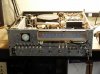
So, I took Echowars' advice and ordered the 25W resistors & hardware he recommended from Digikey. Hooked it all up this weekend, and was very happy with the end result (see below). Connected the dim bulb tester once again, took a deep breath and hit the power switch. The fan roared to life, then a relay click and the fan switched to low speed... and a few seconds later, that sound I've learned to love - the click of a speaker protection relay engaging!

I hooked up a jumper to the antenna terminal, plugged in a set of headphones, and slowly brought up the volume. SOUND!! But only out of the left channel. :dammit: Ah, but what the heck - as long as the tranny's good I don't care - I can fix just about anything else. It was getting late and I didn't feel like diving back in, so I did a quick assessment of what was good and what wasn't:
THE GOOD:
THE NOT-SO-GOOD:
:thmbsp::thmbsp::thmbsp: BUT THE TRANNY WORKS!!! :thmbsp::thmbsp::thmbsp:
The vintage audio gods have smiled upon me - it's been a good day.
So, I took Echowars' advice and ordered the 25W resistors & hardware he recommended from Digikey. Hooked it all up this weekend, and was very happy with the end result (see below). Connected the dim bulb tester once again, took a deep breath and hit the power switch. The fan roared to life, then a relay click and the fan switched to low speed... and a few seconds later, that sound I've learned to love - the click of a speaker protection relay engaging!
I hooked up a jumper to the antenna terminal, plugged in a set of headphones, and slowly brought up the volume. SOUND!! But only out of the left channel. :dammit: Ah, but what the heck - as long as the tranny's good I don't care - I can fix just about anything else. It was getting late and I didn't feel like diving back in, so I did a quick assessment of what was good and what wasn't:
THE GOOD:
- Nice, bright O-scope without a trace of burn-in
- Great tuner - very sensitive and seems to have retained excellent alignment
- Quartz lock works like a charm. Very cool to watch the locking circuitry auto-center the O-scope display after you try to de-tune!
THE NOT-SO-GOOD:
- Dead right channel. Preamp is good, so the problem's either in or after the right channel power amp. Considering all the other spectacular failures in this beast, my money's on melted speaker relay contacts - but we'll see...
- Friggin' fan is noisy - it rattles like the bearings are worn out. Total PITA to replace - assuming I can find a good one somewhere...
- O-scope has an issue - the vertical FM tuning trace is more like two small traces with a center gap. Minor, but irritating. I didn't recap the scope board, but I guess I will now. Probably could use a new set of JFETs as well...
- Still some noise in a few pots and pushbuttons. A little noise in the tuning cap at the low end of the band as well. I already cleaned the heck out of everything once - looks like it wasn't enough.
:thmbsp::thmbsp::thmbsp: BUT THE TRANNY WORKS!!! :thmbsp::thmbsp::thmbsp:
The vintage audio gods have smiled upon me - it's been a good day.
Attachments
Jailtime
Standin' on a corner
that sound I've learned to love - the click of a speaker protection relay engaging!
I love that sound too. I worked for a long time on a Kenwood 9100 that had DC on the power pack outputs. Twas a great day when that relay engaged.
It's really cool that the 2600 is nearly resurrected. I didn't have much hope that it would be when I first saw the Ebay ad.
skibjr
Super Member
Thought you replaced the fan?
Found the exact replacement CT3A2 fans at www.tedss.com for $25, "pulled from a working environment". Thought I'd take a chance anyway and ordered two. Well, the first one hardly turned at all, and the second one turned freely, but had a bit of lateral play. I went ahead and installed the second one, but obviously it's as useless as the first. Bottom line: $50 down the toilet. Live and learn.


skibjr
Super Member
Singin' in Stereo!
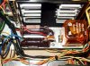
I'm happy to report that I was able to track down the problem with the right channel this afternoon, and for the first time, this ol' girl has her full voice back! It took me a while, but after pulling the amps (yet again) and setting up a bunch of jumpers so I could power them up outside the chassis (pic below) I traced the problem down to a broken foil on the emitter of Q708 in the pre-driver stage.
Fixed up the cracked trace, plugged in the headphones, fired her up - and still no right channel - although now I had all the correct voltages and was getting output at the speaker relay. Turns out the speaker relay's contacts were just about as crudded up as the rest of this receiver when I got it.
Pulled the relay, popped the top, burnished the contacts, blasted 'em with DeOxit and followed that with a few shots of compressed air. Reassembled, resoldered, powered up AND.......... yup, you guessed it, right channel STILL dead. But, I was now getting output at the speaker terminals, just not out of the right side of my phones. Gimme a break already!!
I decided to work back from the headphone jack. I traced the wires to a small PC board mounted above the jack that contains the speaker selector push button switches. Took about ten minutes to wrestle it free from all the damn wires and boards crammed everywhere around it and when I finally got it free, I was amazed at what I saw. There's a pair of 7W 330-Ohm resistors mounted on the underside of this board used to drop the output voltage to a level suitable for driving headphones. The PC board above these resistors was COOKED. I mean crispy-cooked (see pix). I was afraid the board would crumble if I wasn't careful with it. The only way this board could have been char-broiled like that was if whoever used (or should I say abused) this receiver had it cranked to near full output for hundreds of hours. Kind of goes with my theory that this unit did years of hard time in a bar.
Amazingly, the resistors were fine, so I jumpered the crisped traces, reinstalled the speaker switching board, reassembled and installed the cooling tunnel assembly, hooked up the phones and hit the power switch.
STILL NO RIGHT CHANNEL!!!! What the hell!?
Finally, after a bit of consternation, I realized that I had neglected to reconnect the input plug to the right channel. :withstpd:
With relief, I connected the plug and for the first time, heard the legendary Marantz 2600 in glorious, full-fidelity stereophonic sound! Woo-hoo!!!
She gave me no trouble at all during the idle current and DC offset adjustments, so the amp is done. Other than a little fan rattle and a slight double-trace on the O-scope, she's a fully functional receiver. Perhaps next weekend I'll have a chance to address one or both of those remaining issues...
I'm happy to report that I was able to track down the problem with the right channel this afternoon, and for the first time, this ol' girl has her full voice back! It took me a while, but after pulling the amps (yet again) and setting up a bunch of jumpers so I could power them up outside the chassis (pic below) I traced the problem down to a broken foil on the emitter of Q708 in the pre-driver stage.
Fixed up the cracked trace, plugged in the headphones, fired her up - and still no right channel - although now I had all the correct voltages and was getting output at the speaker relay. Turns out the speaker relay's contacts were just about as crudded up as the rest of this receiver when I got it.
Pulled the relay, popped the top, burnished the contacts, blasted 'em with DeOxit and followed that with a few shots of compressed air. Reassembled, resoldered, powered up AND.......... yup, you guessed it, right channel STILL dead. But, I was now getting output at the speaker terminals, just not out of the right side of my phones. Gimme a break already!!
I decided to work back from the headphone jack. I traced the wires to a small PC board mounted above the jack that contains the speaker selector push button switches. Took about ten minutes to wrestle it free from all the damn wires and boards crammed everywhere around it and when I finally got it free, I was amazed at what I saw. There's a pair of 7W 330-Ohm resistors mounted on the underside of this board used to drop the output voltage to a level suitable for driving headphones. The PC board above these resistors was COOKED. I mean crispy-cooked (see pix). I was afraid the board would crumble if I wasn't careful with it. The only way this board could have been char-broiled like that was if whoever used (or should I say abused) this receiver had it cranked to near full output for hundreds of hours. Kind of goes with my theory that this unit did years of hard time in a bar.
Amazingly, the resistors were fine, so I jumpered the crisped traces, reinstalled the speaker switching board, reassembled and installed the cooling tunnel assembly, hooked up the phones and hit the power switch.
STILL NO RIGHT CHANNEL!!!!
What the hell!?Finally, after a bit of consternation, I realized that I had neglected to reconnect the input plug to the right channel. :withstpd:
With relief, I connected the plug and for the first time, heard the legendary Marantz 2600 in glorious, full-fidelity stereophonic sound! Woo-hoo!!!
She gave me no trouble at all during the idle current and DC offset adjustments, so the amp is done. Other than a little fan rattle and a slight double-trace on the O-scope, she's a fully functional receiver. Perhaps next weekend I'll have a chance to address one or both of those remaining issues...
Attachments


Last edited:
There's no current through those resistors unless headphones are plugged in. I'm having a hard time imagining the scenario where that board was so badly baked.
I probably would have removed the resistors and cleaned the top side of the board, and reinforced it with some epoxy.
I probably would have removed the resistors and cleaned the top side of the board, and reinforced it with some epoxy.


87RangerXLT
Tubes Are Timeless...
I'm happy to report that I was able to track down the problem with the right channel this afternoon, and for the first time, this ol' girl has her full voice back! It took me a while, but after pulling the amps (yet again) and setting up a bunch of jumpers so I could power them up outside the chassis (pic below) I traced the problem down to a broken foil on the emitter of Q708 in the pre-driver stage.
Fixed up the cracked trace, plugged in the headphones, fired her up - and still no right channel - although now I had all the correct voltages and was getting output at the speaker relay. Turns out the speaker relay's contacts were just about as crudded up as the rest of this receiver when I got it.
Pulled the relay, popped the top, burnished the contacts, blasted 'em with DeOxit and followed that with a few shots of compressed air. Reassembled, resoldered, powered up AND.......... yup, you guessed it, right channel STILL dead. But, I was now getting output at the speaker terminals, just not out of the right side of my phones. Gimme a break already!!
I decided to work back from the headphone jack. I traced the wires to a small PC board mounted above the jack that contains the speaker selector push button switches. Took about ten minutes to wrestle it free from all the damn wires and boards crammed everywhere around it and when I finally got it free, I was amazed at what I saw. There's a pair of 7W 330-Ohm resistors mounted on the underside of this board used to drop the output voltage to a level suitable for driving headphones. The PC board above these resistors was COOKED. I mean crispy-cooked (see pix). I was afraid the board would crumble if I wasn't careful with it. The only way this board could have been char-broiled like that was if whoever used (or should I say abused) this receiver had it cranked to near full output for hundreds of hours. Kind of goes with my theory that this unit did years of hard time in a bar.
Amazingly, the resistors were fine, so I jumpered the crisped traces, reinstalled the speaker switching board, reassembled and installed the cooling tunnel assembly, hooked up the phones and hit the power switch.
STILL NO RIGHT CHANNEL!!!!
Finally, after a bit of consternation, I realized that I had neglected to reconnect the input plug to the right channel. :withstpd:
With relief, I connected the plug and for the first time, heard the legendary Marantz 2600 in glorious, full-fidelity stereophonic sound! Woo-hoo!!!
She gave me no trouble at all during the idle current and DC offset adjustments, so the amp is done. Other than a little fan rattle and a slight double-trace on the O-scope, she's a fully functional receiver. Perhaps next weekend I'll have a chance to address one or both of those remaining issues...

:ntwrthy: :ntwrthy: :ntwrthy: :ntwrthy: :ntwrthy: :ntwrthy: :ntwrthy: :ntwrthy: :ntwrthy: :ntwrthy: amazing work this is something that will be spoken about for ages to come

There's no current through those resistors unless headphones are plugged in. I'm having a hard time imagining the scenario where that board was so badly baked.
I probably would have removed the resistors and cleaned the top side of the board, and reinforced it with some epoxy.
Maybe someone hooked up a speaker or two to the headphone outputs as monitors instead of using some other method. Or worse, maybe there was a headphone hooked up but maybe improperly plugged in or shorted?
In any case, the board really looked cooked! and split. Probably could use some reinforcement although the resistors themselves look to be holding the board together. Maybe replace with longer lead resistors if space is available and heatsink (if headphones are to be used much, otherwise moot).