• The move to the new server is done. There are some software and database maintenance updates in process. This has us passing the hat around to help out. We appreciate any donations. Seriously, even a dollar helps. The payment page may be found here - https://www.audiokarma.org/support.html

Sad Marantz 2600 - Restorable???

Well, it's gonna be a while before I can get her in shape enough to even think about powering her up, so at the moment, I have no idea what works and what doesn't. However, I've worked on well over a dozen Marantz scope receivers, and to date, I've never seen a dead CRT - so I'm not too worried about this one. On close inspection, there doesn't even appear to be any discolored phosphor (well, maybe just a small center dot), so with any luck, burn-in issues will be minimal as well.

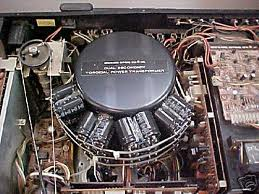
As far as the filter caps - not happ'nin'. These are unobtanium. Wierd working voltages of 105VDC and dual cores (there are actually TWO filter caps in each can); the only way they could be replaced would be through extensive modification of the chassis mounting plate, and the shoe-horning in of four separate caps. The existing filters look pretty good though - no goo oozing out of the bottoms - so perhaps Lady Luck will stick with me in this area as well. I plan to recap most of the rest of the receiver, so the big cans will be some of the only caps I don't replace.

Looks like you dropped by this thread when it was written long ago - http://www.audiokarma.org/forums/showthread.php?t=116273. Still a useful resource though. Some of the Marantz receivers with those damn dual core filters can be modified to accept 4 filters (2285B, 2330B). Doesn't look like this will work with the 2600. Hope your stock filters are still good!
 
Some of the Marantz receivers with those damn dual core filters can be modified to accept 4 filters (2285B, 2330B). Doesn't look like this will work with the 2600. Hope your stock filters are still good!

I could always go this route... :D

2600_filter_fix.bmp
 
Last edited:
I could always go this route... :D

50_1.jpg

That's, um, a little bit unattractive? :D

Wonder if you could restuff the dual core filter shells? How fat/tall are the original filters? I seem to think there was a thread on someone doing it for a 2385 a while back. I'll look for it and post if I can find it.

And look what I found -http://www.audiokarma.org/forums/showthread.php?t=281050 - the restuffing thread! It's for a 2285B, oops. Still an idea...:scratch2:
 
Last edited:
Ya but you got 100v dead nutts to contend with, so you need better than that for the cap. I guess it would run ok with 100v caps, but I would hate to do it.
 
Just thought I'd add a good luck charm :)

Thanks - I'll take all the luck I can get on this beast! Been pretty busy with other stuff lately, and what little I've been able to get done has been relatively unexciting - cleaning tar, nicotine, and dust bunnies :yuck: from all the surfaces I can get to (I've gone through three toothbrushes and two cans of compressed air so far). All pots have had multiple Faderlube baths; all switches have been repeatedly doused in DeOxit Gold. The regulator board has been completely recapped, the dial pointer replaced, and all bulbs replaced. Got lucky and found an OEM soft-start relay on eBay for under $10 to replace the topless, tweaked-up one this unit came with.

Previously, I expressed happiness in being able to remove most of the boards in this thing for cleaning. That was before I tried to put 'em back. :gigglemad This monster is built like a 3-dimensional puzzle - everything has to go back together in a very specific order, or it just don't fit. And the flippin' connectors - all over the place, and completely interchangeable with each other - VERY easy to inadvertently swap if you're not paying attention.

I've attached a shot of what she looks like tonight - the dial assembly, tone amp and selector boards are complete and back in place, as is the scope board and CRT. Actually after all the cleaning, the chassis is starting to look pretty good. To mitigate my pleasure in the accomplishments so far however, I've also included a shot of the worn out lettering on the faceplate. Pretty scary. This ol' girl has seen some use, and I'm gonna bet it was in a bar or nightclub. Not sure what I'm going to do about the faceplate yet, but I'm thinking I'll either have to send it out and pay through the nose for someone to do a custom screenprint job, or figure out how to do it myself. I'm not sure that decals would look original enough or be durable enough to be a satisfactory solution.

I'm hoping to get to the amplifier assemblies this weekend - with any luck, a little courage, and a dim-bulb tester, perhaps we'll be able to run a few electrons through her before month end.....
 

Attachments

  • 2600.jpg
    2600.jpg
    106.6 KB · Views: 299
  • 2600-Face.jpg
    2600-Face.jpg
    105.4 KB · Views: 294
Wow, it's cleaning up nicely! Too bad on the faceplate, those volume markings are pretty well hashed.
 
That's why I hate stuff from heavy smokers. Congrats on the cleaning job so far, looks impressive. I would've done no more than clean the outside, I guess...
 
Thanks - I'll take all the luck I can get on this beast! Been pretty busy with other stuff lately, and what little I've been able to get done has been relatively unexciting - cleaning tar, nicotine, and dust bunnies :yuck: from all the surfaces I can get to (I've gone through three toothbrushes and two cans of compressed air so far). All pots have had multiple Faderlube baths; all switches have been repeatedly doused in DeOxit Gold. The regulator board has been completely recapped, the dial pointer replaced, and all bulbs replaced. Got lucky and found an OEM soft-start relay on eBay for under $10 to replace the topless, tweaked-up one this unit came with.

Previously, I expressed happiness in being able to remove most of the boards in this thing for cleaning. That was before I tried to put 'em back. :gigglemad This monster is built like a 3-dimensional puzzle - everything has to go back together in a very specific order, or it just don't fit. And the flippin' connectors - all over the place, and completely interchangeable with each other - VERY easy to inadvertently swap if you're not paying attention.

I've attached a shot of what she looks like tonight - the dial assembly, tone amp and selector boards are complete and back in place, as is the scope board and CRT. Actually after all the cleaning, the chassis is starting to look pretty good. To mitigate my pleasure in the accomplishments so far however, I've also included a shot of the worn out lettering on the faceplate. Pretty scary. This ol' girl has seen some use, and I'm gonna bet it was in a bar or nightclub. Not sure what I'm going to do about the faceplate yet, but I'm thinking I'll either have to send it out and pay through the nose for someone to do a custom screenprint job, or figure out how to do it myself. I'm not sure that decals would look original enough or be durable enough to be a satisfactory solution.

I'm hoping to get to the amplifier assemblies this weekend - with any luck, a little courage, and a dim-bulb tester, perhaps we'll be able to run a few electrons through her before month end.....

There is a fairly recent thread about someone relettering one, I think it was DIY or Marantz threads....

Russellc
 
I'm not all that familiar with those particular cap cans but I do a lot of work on old antique radios and boatanchor ham gear. Usually they can be carefully cut open and gutted so that new caps can be put inside and connected to the original terminals. Afterwards the can cover is put back on with JB Weld. You can barely tell that it is not original.

There are a number of people that can do this (for not much money). Try googling "capacitor rebuild" or "filter cap rebuild".

Russ WQ3X
 
That's looking very good, at least up to this point. It takes guts, commitment and perseverance to take on a task like this and see it through. So far, you're an inspiration! :thmbsp:

Um, if I were in your shoes, given how much effort this is already requiring, and the ultimate value of the receiver, I'd look for someone to do that faceplate RIGHT, rather than cut corners and do a "hack" on it. In the long run, I think you'll feel better about it that way, even if it costs a bit more.
 
Long Overdue Update...

Well, it's been quite a while since I posted an update on this ol' girl, but it's been really slow going. I keep pretty busy with work, family and other commitments, so it's a rare treat for me to actually get some spare time to get 'into the zone' with this thing for more than a few hours a month.

During the past few months, I've completely torn down, cleaned, and rebuilt the output transistor assemblies and recapped the driver boards and protection board. After considerable deliberation, I decided to use a heavy-duty 3 x 18 AWG cord to replace the missing power cord. Although the conductors are of lighter gauge than the original, the overall visual imperssion is that the cord is worthy of the receiver, and since my Marantz SR18EX (140 watts x 5) uses a similar cord, I'm confident this one will be sufficient to handle the 2600's 2 x 300 watts.

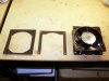
Although I was able to source the correct 5-blade 120VAC Rotron fan, none of the original parts to interface the fan to the cooling tunnel were included in the original receiver purchase - so I had to improvise. The fan is larger than the cooling tunnel, so it needs to be "stopped down" to properly match the tunnel opening. Original 2500 and 2600 models include metal side bars to accomplish this purpose; I was able to find similar brass trim pieces at my local hardware store, which I cut to size (see pic). I was able to fashion a serviceable gasket from an adhesive-backed sheet of child's construction foam I picked up at Walmart. :dunno:

So yesterday, after a four-month investment of precious spare time, I dropped the completed cooling tunnel in place and used the schematic to deduce what wires were supposed to go where (the innards looked like a spaghetti dinner when this beast arrived) and at long last, it was time to plug 'er in...
 

Attachments

  • AmpParts.jpg
    AmpParts.jpg
    76.4 KB · Views: 266
  • Amps_Completed.jpg
    Amps_Completed.jpg
    90.1 KB · Views: 298
  • FanParts.jpg
    FanParts.jpg
    116 KB · Views: 230
  • Fan_Completed.jpg
    Fan_Completed.jpg
    99.4 KB · Views: 206
  • Assemby_Complete.jpg
    Assemby_Complete.jpg
    119.5 KB · Views: 307
...but it was getting late, so I wimped out and closed up shop for the night. I figured that if I DID plug her in and she didn't work, I'd spend a sleepless night wondering what the hell I did wrong... :gigglemad

Had some more time this afternoon, so I picked up where I left off. Thought I would exercise a little self-discipline and triple-check some of my work before I pulled out the dim-bulb tester and attempted to apply electrons. Turns out it was a good thing I did.

I had taken some pictures of my work on the output transistor assemblies, and I decided to compare them with photos of the original stock assemblies just to make absolutely sure I didn't do something stupid like switch an NPN for a PNP somewhere among the 16 outputs. No problem - with the outputs. However, a quick cursory check of the tunnel-mounted drivers in the photos confirmed that I had indeed switched the MJE15033 and MJE15032 in each channel! :dammit:

Took a deep breath, disconnected everything, pulled the power amp assembly, disassembled the cooling tunnel, switched out the transistors, and put it all back together again. As irritated as I was though, I was glad I caught the screw-up before I tried to apply power. I could easily have fried each and every output on both boards - and let me tell you - I can conceive of NO receiver being more of a pain-in-the-a$$ to install output transistors in than the Marantz 2500/2600! :yes:

So, once again ready for power-up. I thought I'd just take a few more static resistance measurements here and there to make sure there were no obvious shorts anywhere. While I was checking resistance of the rail feeds to ground, sure enough, one of them was a dead short. (Insert favorite expletive here)!!! That meant either a shorted filter cap or a shorted rectifier, and fortunately, it turned out to be a shorted bridge rectifier module. I was lucky enough to find an OEM replacement online, and I should have it by the end of the week. :) Keep your fingers crossed - hopefully she'll be singing again soon!
 
Nice job! Sounds like you'll have that beast making music again before long. :thmbsp: Yeah, I know it's "just a stereo", but this one was worth the save, and all of your time invested, I think. Not too many 2600s out there, and now you have yourself a fine one. You are a great inspiration for those of us with similar monster receivers tucked away in closets and storage units, too lazy or too good at procrastinating to finish 'em off! (looking in the mirror) :D
 
excellent progress:thmbsp:. Good job not hurrying to apply power. With an investment like your's, every detail should be checked.
 
Although I was able to source the correct 5-blade 120VAC Rotron fan
Hi Skib, The correct fan in fact is a "Centauri". Yeah tracking down those mounting pieces can be pretty challenging. I talked with my tech this morning and he told me that he is getting close to finishing my 2500. I'm not going to use the dancing banana just yet, while keeping my fingers crossed. :yes:
 
Back
Top Bottom