• The move to the new server is done. There are some software and database maintenance updates in process. This has us passing the hat around to help out. We appreciate any donations. Seriously, even a dollar helps. The payment page may be found here - https://www.audiokarma.org/support.html

Kenwood KA-4006 "new to me" not working

Status
Not open for further replies.
speaker terminals

Well, I had envisioned copying these binding posts. But, because for the KA-4006 this would require cutting metal on the back panel and also because of time constraints I have put this on the back burner. I have one or two other amps that I would like to install binding posts on. Maybe I will do them all together at some point.


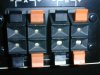
The KA-4006 original speaker terminals have, IMHO, a couple design flaws:

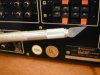
(1) The holes are small. In the first pic the two holes on the bottom right have been enlarged but all the others are original. I had difficulty inserting freshly and cleanly stripped, 16 gauge stranded wire (lamp cord) into the holes. A strand or two would deflect each time I inserted the wire even though I had the benefit of good lighting and the amp was facing me, easily accessible on my work bench.

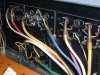
(2) In the positive (red) terminals the hole centers for left and right channels are only about 3/8" apart. Pic 2


It seems to me that the combination of small holes and close spacing creates an increased likelihood of shorting the speaker wires due to errant strands coming into contact with each other. This amp, in particular, did come to me with blown main output transistors in one channel. Makes me wonder if this might have been the cause, or if this is a common occurrence in other Kenwood amps with similar speaker outputs.

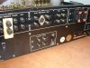
In my amp the springs inside the terminals are all still strong. I shaved away plastic to enlarge the holes. Pic3. Stranded 16 gauge goes in easily now. Cleaned inside of them with Deoxit and the special Deoxit brush.
 

Attachments
  • DSCN0001a.JPG
    DSCN0001a.JPG
    117.9 KB · Views: 40
  • DSCN0006 3-8 inch spacing.JPG
    DSCN0006 3-8 inch spacing.JPG
    59.2 KB · Views: 41
  • DSCN0009.JPG
    DSCN0009.JPG
    54.1 KB · Views: 46
Last edited:
back panel

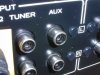
Cleaned up all the RCA's inside and out. Deoxited the Normal/Separate switch.
 

Attachments

  • DSCN0011.JPG
    DSCN0011.JPG
    129.8 KB · Views: 35
  • DSCN0019.JPG
    DSCN0019.JPG
    127 KB · Views: 31
  • DSCN0024.JPG
    DSCN0024.JPG
    135 KB · Views: 32
  • DSCN0021.JPG
    DSCN0021.JPG
    139.9 KB · Views: 25
Last edited:
main amp board done!

Heat sink and main outputs installed. Bias set to correct values with new Bournes trim pots (big improvement). Have been listening to the amp for a couple weeks - no issues, sounds very good.

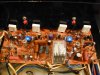
Pic1: Main amp board installed, for good hopefully, with many new components showing. In the upper middle of the pic one resistor appears to be almost touching a transistor...it wasn't...but I did straighten it up better after the pic.

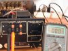
Pic2 and Pic3: Left and right channel DC offset readings after 20 minutes warm-up. Both channels are around 9.5 mV when the amp is first turned on. But they settle in nicely after a while and stay there :D
 

Attachments

  • DSCN0019.JPG
    DSCN0019.JPG
    122.5 KB · Views: 57
  • DSCN0016.JPG
    DSCN0016.JPG
    117 KB · Views: 57
  • DSCN0012.JPG
    DSCN0012.JPG
    119.9 KB · Views: 54
Last edited:
Well, I had envisioned copying these binding posts. But, because for the KA-4006 this would require cutting metal on the back panel and also because of time constraints I have put this on the back burner. I have one or two other amps that I would like to install binding posts on. Maybe I will do them all together at some point.


The KA-4006 original speaker terminals have, IMHO, a couple design flaws:

(1) The holes are small. In the first pic the two holes on the bottom right have been enlarged but all the others are original. I had difficulty inserting freshly and cleanly stripped, 16 gauge stranded wire (lamp cord) into the holes. A strand or two would deflect each time I inserted the wire even though I had the benefit of good lighting and the amp was facing me, easily accessible on my work bench.

(2) The positive (red) terminals are only about 3/8" apart. Pic 2


It seems to me that the combination of small holes and close spacing creates an increased likelihood of shorting the speaker wires due to errant strands coming into contact with each other.

You are doing a great job, with nice reporting here !

Well, the binding posts of most amps of those days had those increadable small sized holes, one wonders if such very small AWG speaker cables were really the standard in those days. I have been thinking a lot about replacing binding posts for several amps, but it is a trade off between decent binding posts and maintaining the original design of the unit (hard to choose sometimes). Sometimes I wondered if they could be drilled out to a larger diameter (when done gently it might not be visible)

The non-insulated binding posts in EW's thread are a nice piece of work (it gave me some ideas), but I would fear shorting them sooner or later, so I would go for insulated posts in any case.

PS: excellent post #80, you really show the difficulties one can have and the choices to make. Good idea of the duct tape and wooden blocks !!

So, what's the next project? :D
 
Last edited:
Thanks for your words of encouragement Oilmaster :)

Well the next project will be a Sansui AM-9 that has a non-standard topology. It has a servo, the purpose of which I do not know. But the servo is implemented with an STK. The AM-9 does have standard type output transistors, two of which I blew when connecting to a bad speaker. But that is a whole 'nother story for a later time and a different thread...


Still have a way to go with the KA-4006 though: power supply, tone board and pre-amp board. I already have the new main PS caps as you know. Of course, when finished with the electronics I also intend to clean up the exterior. Plenty more posts coming in this thread :thmbsp:

Regarding the speaker terminals, it turns out that the plastic was the limiting factor. The metal jaws inside open much wider than the size of the hole in the plastic that encases them. So no drilling was required in order to enlarge the holes, just removing a bit of plastic.
 
Last edited:
Amplifier for sale...

Many new parts!! May require some re-assembly...


picture.php


:D just kidding
 
Last edited:
need some advice choosing a capacitor sub on the tone board

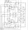
Capacitors Ci5 and Ci6 on the Tone Board are bipolar 6.8uF 10v (schematic below)

These caps are the output caps for the tone board so I would like to put the best in there that I can. (I used Elna Silmic II for the input caps to this board.) But I am not finding matches, of any quality, for the output caps. I searched for film first but those were all too large physically. And the bipolar electrolytics available at Digikey and Mouser are not perfect matches electrically.


Panasonic SU 10uF 16v
http://search.digikey.com/scripts/DkSearch/dksus.dll?Detail&name=P1163-ND

Nichicon MP 10uF 10v
http://www.mouser.com/ProductDetail/Nichicon/UMP1A100MDD/?qs=sGAEpiMZZMtZ1n0r9vR22bYzEsjb8gAO8OU/nZbBmjg=


DC input to the Tone Board is +/-14v


My questions are:

1) Is it OK to go up from 6.8uF to 10uF in this location?


2) Would it be preferable to stay with the original 10 volt rating and use the Nichicon MP - a very tiny cap at 4mm Dia x 5 mm Height. Or the Panasonic SU which is physically larger at 5mm Dia x 11 mm Height but which also has a higher voltage rating than the original cap?


3) is there some option I haven't considered that would be better than the above?

.
 

Attachments

  • !tone amp enlarged 266 in pdf.JPG
    !tone amp enlarged 266 in pdf.JPG
    45.3 KB · Views: 29
Last edited:
thanks Alienz

I am learning so much from the generosity and experience of others...I hope that in return my posts may be helpful to someone.
 
Last edited:
Capacitors Ci5 and Ci6 on the Tone Board are bipolar 6.8uF 10v (schematic below)

These caps are the output caps for the tone board so I would like to put the best in there that I can. (I used Elna Silmic II for the input caps to this board.) But I am not finding matches, of any quality, for the output caps. I searched for film first but those were all too large physically. And the bipolar electrolytics available at Digikey and Mouser are not perfect matches electrically.

3) is there some option I haven't considered that would be better than the above?

.

These caps are in the signal path, and this might be a good oppertunity to do some testing, after listening to it for quite some hours each time. Being, 1)putting some additional bypass film caps across the new caps, soldered on the other side of the PCB (plenty of space), and 2) exchanging these caps with different brands/series.
 
Hey Oilmaster :)

I am aware that these caps are in the signal path when the tone circuit is switched in. Otherwise, (I believe) the first and only capacitor the signal sees is the new poly that I installed in the amp input locations.

I have ordered Nichicon Muse ES for the bipolars on the tone board.

Regarding testing, with and without bypass caps and with different brands... frankly I just don't have the time to do that kind of testing. I agree that it would be very interesting to do.
 
Last edited:
phono board

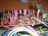
Wima MKS 2 Polyester Film caps in signal path. Nichicon PW everywhere else.

Wima 3.3uF in Cd1, Cd2 input positions
Wima 1uF in Cd13, Cd14 output positions

The new Wima input caps are 63V, the original tantalums were only 10V. Increasing voltage in a film cap is not an issue is it?

.
 

Attachments

  • DSCN0085!.JPG
    DSCN0085!.JPG
    127.2 KB · Views: 106
Last edited:
turn on/off thump - is this related to relay timing?

I don't think this was always there. The first time I tested the amp with just new output transistors (before working on the main, tone, or phono boards) I did pay attention for any weirdness and noted that there was none. But regardless of when or if this was caused by some of the work I have done, I would like to resolve this if possible.

I did an advanced search for threads with "thump" in the title and got about 65 hits. The bulk of these cases involved either relay-less amps or capacitor coupled output amps (KA-4006 is neither). Of the remaining cases, the most-discussed possible causes were either speaker relay or imbalance in charging/discharging of main PS caps. As of now I have not done anything with the PS on this amp. There is a .2 volt discrepancy in the output of the two zeners that regulate voltage to the tone and phono boards, but I don't see how this could be causing this problem :scratch2:

Obversations
Thump in speakers when turning amp on/off. I measured DC on the speaker outputs using the MAX function on my DMM. Numbers stated below are rough averages of several readings in DC volts:

L-On L-Off
-2.38 .108

R-On R-Off
.432 .080

DC offset after 10 minutes: L .004V / R .001V

These are not horribly bad numbers I am guessing, because the thump is not that bad either. But because of the timing of the relay I am wondering if it is not possible to make this thump go away?

When turning the amp on the relay contacts close (engage) after only one second or less. And when turning off the amp the relay opens after about 4 seconds. I have compared this behavior with four other amps, and the relay timing in all of them is the opposite, i.e. in all of the other amps the relay engages about 3-4 seconds after the amp is turned on and opens in less than a second when the amp is powered down.

If the on/off timing of the KA-4006 relay was similar to these other amps, would this solve the thump problem? Or is this not the right approach to eliminate the turn on/off thump?

If this would solve the problem, is there something I could do to tweak the behavior of the speaker relay in the KA-4006 to get it to wait longer before engaging and also to disengage faster on power down?

I don't know, maybe change a resistor value, or swap a transistor for one with lower/higher gain.... or ???


Note previous, potentially relevant discussion in this thread:
- main board schematic post 77
- relay modification posts 49, 57, 58, 65
- Qe25 originally 2sc1416 replaced with 2sc1845F post 77


...thanks in advance...

.
 
Last edited:
Hi roger2

I would agree that the switch-on and switch-off delay is odd.

Looking at the circuit around the relay it is Ce26 which would normally delay the switch-on of Qe26 (and therefore the relay) once it is charged via Re56. However, There is another connection point (10?) at the bottom, where is that going to/ comming from? This is important to know before doing further analysis.

In the mean time... let's try to do some collective circuit analysis. Please anybody drop in (don't shoot) if I'm wrong here...

Qe25 is the protection transistor. In case of a high output voltage ('monitored' via Re54/Re53), it will switch on and quickly discharge (short) Ce26 to ground, effectively switching off Qe26 (i.e. switching off the relay). Ce25 is there to filter out the AC voltage (attenuated by Re54/Re53) to obtain only a 'clean' DC voltage applied to base of Qe25 (tripping is based on exceeding a certain DC voltage, albeit it is monitoring only the positive half of both output signals). Any residual AC voltage could trip the protection circuit too early.

The existance of the two diodes De6 and De7 is bit more difficult to define. Hmm, have to think about that. Anybody? :scratch2:

There are a couple of failures possible here to explain your problem. Quick switch-on indicates that the base voltage of Qe26 is (almost) immediately high, like if Ce26 would not be there. Slow switch-off indicates the opposite; the base voltage of Qe26 stays high, like if Ce26 is there (in good condition) and the base voltage of Qe26 depends on discharging of Ce26 via Re57 and Re58.

Hey hey !! that might explain the existance of De6 and De7: I can image that they are there to switch off Qe26 immediately when the amp is switched off. In that case the output stage voltage drops to zero and the diodes 'short' (with 1.2 volt voltage drop) the base voltage of Qe26. If one of the diodes is broken (i.e. open) then this would explain the slow switch-off.

In other words: check the health (and orientation if you installed new ones) of electrolityc capacitors Qe25 and Qe26. Then, check the health of both diodes (or just replace them with 1N4148 diodes to rule out any anarchy).

Also, just to make sure, reflow all solder joints, notably of the resistors.

If you did any soldering previously around this circuit, make sure all flux has been well removed (could cause resistive conductive path) and that there are no accidental shorts by soldering.

PS; once again, you have an excellent way of writing your thread.

PS2: the Wima caps look great; good choice :D, and the increased rated voltage has no impact in case of film caps.

cheers,
ozzy
 
Last edited:
Forgot about the initail question; the turn on/off thump...

I could imagine it is related to the inverse-acting relay circuit. As the amp is a dual rail design, without output coupling capacitor, there should be no thump.

One possible cause for the thump is monitoring circuit (Re53/54, Ce25) which interconnects the output circuits of both channels and which contains a charging element (i.e. Ce25). So, a couple of question arise... did you change the capacitor? Did you keep the same value? Are the resistors in good shape/right value?

Also, the monitoring circuit could be healthy, and the associated relay circuit might inject some current in the monitoring circuit during switch-on. Therefore, referring back to previous post, double check the diodes and/or replace them.


In one of your pics, is that a new 220uF capacitor instead of 100uF value in the schematic?
 
Last edited:
I purchased a couple of original service manuals last week, including one for this KA-4006. Nice surprise turned out to be the inclusion of:
- Service Bulletin SB 2016 for KR-4400/KR-5400/KA-4006
- SM Supplement for KR-4400/KR-5400/KA-4006

This is finally giving the answer to why in other trheads were soem folks were looking at different PCB numbers while talking about the same unit model.

I scanned both documents in JPG (as below) and PDF (attached), and I will send them to the AK database as well.

The service bulletin is only about the new protection circuit and explaining how it works. What else do want talking about it! I was mostly right in my explanation in previous posts, and now the existance of the double diode is clear as well: they cover the protection function for the negative cycle part, as where the transistor covers the positive cycle part. Logic after all...

Now, coming back to your inverse-acting protection relay, perhaps it is related to the additional fly-back diode you added. True that such diode is found 9 out of 10 times across a relay, but as the SB states, the (odd/rare)zener diode has been defined there for a special reason in this circuit. So, perhaps there is an unwanted interaction between the zener diode and flyback diode. I would suggest to desolder one leg of the flyback diode and see what the difference is.

cheers,
ozzy

KA-4006SB2016pg1.jpg

KA-4006SB2016pg2.jpg
 

Attachments

Status
Not open for further replies.
Back
Top Bottom