• The move to the new server is done. There are some software and database maintenance updates in process. This has us passing the hat around to help out. We appreciate any donations. Seriously, even a dollar helps. The payment page may be found here - https://www.audiokarma.org/support.html

DIY Simple Active Preamp

If you're using batteries won't you be running +/- 9V? I was planning on using a +/- 10V filtered PSU that I have but now I see the 12V recommendation.

It will "run" on anything down to 6volts per side but if you are using a PSU you may as well have 12volts per side minimum IMO.

I'd recommend if you are building a PSU to have it 15volts per side as it can be used on other projects as well. Such as the CNC.
 
Yeah, i knew that - i am not concern about the cost. I just like point to point as i am a tube guy. I know it's kind of hassle having to draw the schematics since everything is there on the board. Thanks.
 
Yeah, i knew that - i am not concern about the cost. I just like point to point as i am a tube guy. I know it's kind of hassle having to draw the schematics since everything is there on the board. Thanks.

This is schematic I designed for CNC phono stage as well as SSP board. Used lower part for any voltage up to +15, 0 , -15 using 5K trimmers at adjustment terminals.


Uploaded with ImageShack.us

This is SPP schematic.


Uploaded with ImageShack.us
 
Last edited:
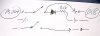
Cool... Many thanks. The power supply caps seem small - are you sure it only need 10uf and not 100uf. I modified your to make it easier to understand (for me) - does it look right. Thanks
 

Attachments

  • sosimple.jpg
    sosimple.jpg
    90.3 KB · Views: 259
Cool... Many thanks. The power supply caps seem small - are you sure it only need 10uf and not 100uf. I modified your to make it easier to understand (for me) - does it look right. Thanks
Yes that 10uF is correct, still 100uF does not add any value. Your diagram is correct.
 
Thanks omishra. I will start gathering part. With 10uf value, i can actually build this pre without any electrolytics.... Nice !!!
 
Not to muddy the waters but my design had 100uf caps on the supply rails but using 10uf is the lower limit IMO.
 
I will try with 10uf and 100uf to see if it would make any different in sound.

Did you say the 100K can be obmit "With the 100k, it may be redundant in most systems but it's a "just in case" thing.

Thanks for the sharing this with us. :thmbsp: :banana:
 
I measured the output and without the cap it has 1.1mv DC with it zero and to me there was no difference in the sound.
Hi, I built this using 8k2 and 10K feedback resistors. Powered with +/- 12V dual PS. I am getting equal current drawn from both the rails. Output is sounding nice with DC blocking of 2.2uF WIMA Caps.

I measured output DC on output pins of OP AMP. Its 12V there wrt ground.:worried: Is this correct? I find no issues in IC or any connection. same IC works great in CNC with DC offset of 10mV.

@HypnoToad: Can you please measure in your SSP build & confirm? I must be using DC blocking cap.

Edit: When I measured output DC voltage before 2.2uF cap, input terminals were disconnected and floating in air. That was making oscillations. I can hear hum and speakers cones on verge of popping out. After connecting to source I could not try to measure the same again. So it means keeping output DC blocking cap is good idea.

BTW, I am using both feedback resistors 10K and near to PASS-B1 sound.

Another finding: If you add that 25K pot at the input then DC offset is equal to 0-3mV. That means I was missing ground reference at the input.
 
Last edited:
My parts are beginning to roll in. I will have this done before my B1 Hypno!

I even have my volume knob!!! :D

I hope I don't screw-up drilling through the metal case.
 
Question: Where do I connect the LED? Is the best place to either side of the PS output, after the on/off switch?

The long leg of the LED is positive, and you can connect the resistor to any leg. It goes on the PCB side of the switch between the positive and negative outputs.
 
The long leg of the LED is positive, and you can connect the resistor to any leg. It goes on the PCB side of the switch between the positive and negative outputs.

Not sure if this is right. Shouldn't it go across voltage and ground like this?
 

Attachments

  • IMG_9055.JPG
    IMG_9055.JPG
    69.6 KB · Views: 130
Last edited:
Not sure if this is right. Shouldn't it go across voltage and ground like this?

It goes from the positive and negative outputs from the switch, ignore the ground point altogether. Just make sure the longer leg goes to positive.

LedSchem.jpg
 
I hereby confirm that there is no major DC offset voltage at the output.

Open input lead with source connected and without any grounding resistor between input and PS ground makes floating input. This confuguration puts DC offset at the OP-AMP output pin, equal to supply +Vss.

At the input you have to either use 25K pot (wire pads marked CW, W, CCW on PCB)
- or -
If you don't want to use volume control pot then add 1M ohm shunt from input (wire pad 'W') to ground (wire pad 'CCW') of each channel. This makes PS ground reference at the input of OP AMP. Resulting output voltage offset is 0.1-0.3mV (DMM reading is fluctuating).

Is there anybody to confirm 10uF and 100uF at PS pins does not makes audible differences? I did not find any differences.
 
I am sorry omishra, I cannot answer your question. How do I measure offset? I just completed mine and doing first-listen now. I noticed that if I power on with power amp turned on, there is a big transient and the amp (chip amp in this test) relay trips. I powered back up without problem.

I am using a 20kOhm stepped Ebay attenuator.

Only doing low level listening now, it is 1:40 AM.

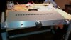
Here are a couple of quick shots:

attachment.php


attachment.php
 

Attachments

  • SSP_front.jpg
    SSP_front.jpg
    82.3 KB · Views: 574
  • SSP_back.jpg
    SSP_back.jpg
    89.8 KB · Views: 567
^^^ Its nice looking amp. Congrats.
I haven't noticed that turn-on pop. May be my PS is taking 30sec to fully charge its power caps. Thanks to inline 525 DCR of inductor coils.
 
Back
Top Bottom