• The move to the new server is done. There are some software and database maintenance updates in process. This has us passing the hat around to help out. We appreciate any donations. Seriously, even a dollar helps. The payment page may be found here - https://www.audiokarma.org/support.html

Oye! Time for another 9090DB resuscitation!

w1jim

I can fix it but good...
Subscriber
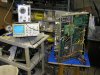
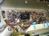
I picked up this project 9090DB from AKer "Steelman" a few weeks ago.
I knew it wasn't working but all the parts were there so how hard could it be? Well, I never read the multiple posts extolling the hassles with the Dolby circuitry on these. Oh well, another challenge.

So far I've recapped most of the amp PCB and the power supply regulator. I've resoldered the Dolby board but don't know if I want to recap it - the less I touch it the better and I'm certain I'll never use the circuitry.

On the PS board I found that 2 - 1 ohm resistors were bypassed with wires and one resistor was just hanging in the air with an end detached.
Ultimately I'll recap most of this and replace all of the bulbs with LEDs.

Currently I have the power amp and power supplies working and audio coming out of the Dolby PCB but I don't think I've got it on the tone boards. The tuner appears to work too.
I've been sending a sine wave into the AUX input and then tracking it with my scope so it shouldn't be that hard to find where it drops out.
I go with the theory that most problems are quite simple though a bitch to find.

I'm on the road for work over the weekend but I'll bring the service manual and have some time to ponder.

Some pictures for your entertainment...


attachment.php


attachment.php
 

Attachments

  • P8260965.jpg
    P8260965.jpg
    118.8 KB · Views: 598
  • P8260964.jpg
    P8260964.jpg
    114.8 KB · Views: 357
Register to hide this ad
Good luck with the restoration. It looks like you've got it under control. :thmbsp:
That's just my power of illusion at work.
Judging by the silly stuff on the power supply board I'm ready for something weird like disconnected or rerouted signal leads :smilemad:.

This one is to fill out my collection of early TOTL receivers (SX-1010 & 2325).

Stay tooned!
 
Wow!! Ive been there before.....................
Your patience and perseverance will pay big dividends, and victory will be sweet..............
Another Classic brought back from the dead............
I will be watching with keen interest.
 
Copied for reference from a posting by CDfixer/Jim:

Signal flow through the 9090db receiver is

Input board and selector switch
Dolby board and switch and tape monitor switch board
Loudness and -20DB mute switches
Volume and Balance controls
Tone control and filter switches
Back to the input board, and preout to main jumpers
Driver board and outputs
Protection board and relay
Speaker selection switch
Speaker terminals.​
 
Say Jim (said the voice in my head) how are you doing with that there 9090DB?

After resoldering the dolby PCB I traced the audio signal to the input of the op amps on the tone control PCB and then realized they weren't get any power - the power supply regulator board has issues.

So far I've replaced all of the electrolytics on the PS board and 2 bad transistors.
TR04 / 2SC1211 replaced with a 2SC1318
TR01 / 2SD438 replaced with a KSC2383

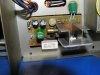
On the tuner regulator PCB I recapped everything and replaced the 2SD313 with a KSC2073 - not because it was blown but just as an upgrade. There was also an electrolytic cap mounted very close to the heatsink that I moved out by about half an inch.

The zener on the PS PCB tests OK. I think I'm going to stare at this for a while before I plug it back in.

More to come...
 
Last edited:
It's alive!!

It's alive!
I finally got enough courage to plug 'er in this afternoon and after a few touch ups on the tone board got the tunes out of it. (YAY :banana:).

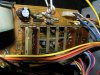
I installed 25 turn pots on the amp driver PCB which made dialing it in a breeze; no more turn it a 1/10th of a hair to overshoot the settings.

Next step is to check the resistor on the protection board for the green LED (extremely dim). It could also be a contact on the relay.

I still need to recap the tuner and phono EQ boards. Each will represent a challenge - the tuner is rather densely populated and the phono appears to be intertwined with the input selector switch.

I'll be replacing all bulbs with LEDs including using different colors for all of the different input select indicators. I'm thinking of using amber LEDs for the power meters.

Some new pix of the driver board and the tuner regulator board showing how I moved one of the caps (the gold one) away from the heatsink.

We're getting there....


attachment.php


attachment.php
 

Attachments

  • P9010966.jpg
    P9010966.jpg
    104.5 KB · Views: 329
  • P9010967.jpg
    P9010967.jpg
    79.2 KB · Views: 259
Nice job with the bourns trimmers, sure does make it easy to make those fine adjustments.............
Lookin good...................:thmbsp:
 
that wasn't the voice in your head, that was me

Say Jim (said the voice in my head) how are you doing with that there 9090DB?

After resoldering the dolby PCB I traced the audio signal to the input of the op amps on the tone control PCB and then realized they weren't get any power - the power supply regulator board has issues.

So far I've replaced all of the electrolytics on the PS board and 2 bad transistors.
TR04 / 2SC1211 replaced with a 2SC1318
TR01 / 2SD438 replaced with a KSC2383

On the tuner regulator PCB I recapped everything and replaced the 2SD313 with a KSC2073 - not because it was blown but just as an upgrade. There was also an electrolytic cap mounted very close to the heatsink that I moved out by about half an inch.

The zener on the PS PCB tests OK. I think I'm going to stare at this for a while before I plug it back in.

More to come...
 
that wasn't the voice in your head, that was me
Yowser - then you've got more issues then I do - damn those crazy things you've been telling me to do!

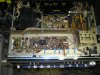
Recapped the phono EQ PCB today, it was a real joy pulling the caps out from between the sections of the input selector switch. Also the flexible PCB that ties it to the "Pre out" / "Amp in" RCAs tore so I replaced it with some 20 gauge wiring.


attachment.php
 

Attachments

  • P9020969.jpg
    P9020969.jpg
    96.7 KB · Views: 230
Home stretch!

Recapped tuner PCB - replaced all electrolytics.
Replaced tantalums with electrolytics
Replaced electrolytics and tantalums of <1uf with poly caps.
Replaced all bulbs with LEDs
Replaced power on LED with a larger "frosted" 2-color LED.
Power meter has yellow LEDs.

Time to pay a little attention to the case after some more burn in (and hopefully not "up").


attachment.php
 

Attachments

  • P9030971.jpg
    P9030971.jpg
    115.6 KB · Views: 41
  • P9030972.jpg
    P9030972.jpg
    110.8 KB · Views: 44
  • P9030973.jpg
    P9030973.jpg
    87 KB · Views: 232
So how did you do the LED's?
Did you incorporate a bridge rectifier for the supply to the LED's?
Or did you use the AC supply.
What voltage LED's did you use?

It looks like a terrific result, I have been meaning to do that to my G-7700's.
 
I've been getting most of my LEDs from this company:

http://c-leds.com/store/

They're in the USA and have great prices.

They are not like the LEDs that some AKers have been selling with wire leads and resistors incorporated in them; these are the raw leaded parts that you'll have to fit yourself.

For the power meters I put the yellow ones in series (-/+ -/+), and replaced the two 10 ohm resistors on the meter PCBs with a 20 ohm resistor. You may want to try a 27 or 33 ohm resistor there as in my testing I blew a few of these.

For the LEDs for the function indicator bulbs I put a 120 ohm resistor in series. To hold those LEDs in place i used a touch of 5-minute epoxy.

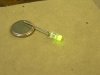
For the dial and tuner meter LEDs I took 2 white, wide-dispersion LEDs and put them in series and then soldered them to end caps from some blown fuses and then snapped them into place.

These were all AC lines so there is a little bit of flickering which may or may not bother you. If so then a simple rectifier (or bridge rectifier) and a smoothing cap (470 uf would be ample) would address this.

The power light on these is a 2-color red/green LED. Red for protect / power up and green for ready. I found that the green wasn't very bright - this was a result of pitted relay contacts - the speaker protection relay is a 3 pole affair. One pole for the green LED and the other 2 for the speaker connections.
I burnished the contacts for all 3 poles (and also cut the ground trace for the "at rest" position for the speaker poles) to avoid a situation where - during a malfunction - the amplifier output is routed to ground (not good).

While I kind of like the older LEDs that have a small square of material that you can see glow I replaced the power LED with a special Siemens brand LED that has a frosted lens. My prior employer built police tracking devices (essentially direction finding equipment to locate stolen vehicles) and they used these in that application. When they went out of business I snagged a couple hundred of these. I've used them in various projects and they are a bit of a signature of mine.
JimB


attachment.php
 

Attachments

  • P9030974.jpg
    P9030974.jpg
    57.6 KB · Views: 131
I can't believe that is the same unit...Absolutely amazing :thmbsp:
Thanks Vince, and thanks for selling it to me (insert Barter Town plug here).
I've always said that if I can't fix it I can fix it so nobody can fix it. On this one at several times I was about to go to the dark side.
 
Thanks Jim, for the very informative post on the LED retro-fit.
Gives me a few ideas for doing mine. Although mine will be easier because there are only two bulbs in a G-7700.
 
Back
Top Bottom