• The move to the new server is done. There are some software and database maintenance updates in process. This has us passing the hat around to help out. We appreciate any donations. Seriously, even a dollar helps. The payment page may be found here - https://www.audiokarma.org/support.html

SX-1980 rescue

The stock thermal fuse is set for 109°C (229°F) and is rated for 15A. The exact replacement would be an NTE8108, and Parts Express carries it. Cheap by itself, but you'll get hozed on shipping unless you need other stuff from them.

Digikey also carries a Cantherm thermal fuse rated for 15A and set to trip at 104°C (220°F), which would work fine. Part number 317-1130-ND.

Your fuse is too hot. That, and most thermal fuses are not rated for the kinds of current that they will be required to endure in the 1980. Most are rated for a couple of amps at best...the two I listed here are designed for a full 15A continuous duty, and much more for brief surges.
 
Last edited:
Thank you sir. I also am wondering if I need to change, (reduce) the emitter resistors to allow for proper biasing of those new outputs. It also appears that soldering in the new thermal fuse will take a really quick and hot iron along with heat clamps or it will become a repeat process. You have been a great help so far btw.
-Lee
 
Last edited:
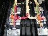
Completed amp module thanks to EW and MTF and their unfailing assistance. New outputs, new insulators, transistor mounting pad surfaces wiped, checked for any burrs, cleaned and new thermal grease, new tie downs, screw height verified for balanced tension on the brackets with micrometer, all potential faults to ground double checked, wire tied cables and inside connectors cleaned of any contaminants. Soldering could have been a little neater I suppose however with the heat sink clamps on the terminals it got pretty tight in there and I did not want to stress anything during the process. Glenn and Mark, if I missed anything please let me know so I can redo this as needed. This board certainly has the potential to produce a magic kingdom worth of magic smoke if assembled incorrectly.
-Lee
 

Attachments

  • driver1.jpg
    driver1.jpg
    85.3 KB · Views: 135
  • driver2.jpg
    driver2.jpg
    82.4 KB · Views: 138
The clamps are a waste of time and effort on a power transistor, unless you're taking 15+ seconds on each connection. A dab of paste flux and hit it with the solder and iron, and you're done with each connection in about 3 seconds.

Same with the thermal fuse. Use flux to help the solder to flow quickly and evenly. Should not take but about 3 or 4 seconds for each connection, but wait 2 or 3 minutes after you solder the first side before you tackle the second.

I detest the 'put a 'J' wrap on a wire & hit it with solder' method of attaching a wire to a post or a transistor lead. It screams novice, or a pro who doesn't care. But it's your amp, not mine. If I ever do another one, I have ideas to make a neat and easily soldered/desoldered connection to those transistors.
 
Understand about using the j-wrap method of securing the wires. The smallest rings I could find were for #4 studs, which did not work in this application. If you have a source for rings that will better fit the bill please let me know. I have no qualms about reworking the wiring. Thanks also for the heat sink advice. Ditto the thermal fuse p/n a couple of posts ago.
-Lee
 
Here ya go, budget ring tongue: http://dkc3.digikey.com/PDF/US2011/P0400.pdf

I think I used the A28261-ND, but I used a grinder to make the outside of the ring 'flat' on each side for more clearance between connections. And I bent them apart a bit. You could use shrinkwrap and insulate them all...
 
Last edited:
538-19069-0027

used them, they show up in my pictures

not bragging, ordered up a pile of them.
 
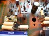
The rings were perfect. Also finished up the driver board.
-Lee
 

Attachments

  • 1980outputrings.jpg
    1980outputrings.jpg
    82.4 KB · Views: 216
Last edited:
Onwards into the power supply. Replaced the 35v zeners with 17/18 500ma per the service bulletin. Used the dbt to power up receiver. No issues so far. Plugged into mains power to check power supply voltages. Crud, no -80v on pin 18 and no -34 on pin 11. Plus side of the board is fine. Backtracking the circuit leads me into that pesky 2sk34FET. Suspicious of those 24v zeners I will change out d210,d211 and test again. Any other suggestions would be appreciated, this particular circuit is a bear.
-Lee
 
Do your research. :nono:

Answers are out there to find.

EchoWars current source, not (unobtanium) jfets.
(He makes them, I make them)

extra zeners and stuff come out as well.

all new power transistors needed: mje15032/33's

lots more small stuff.

hint:
http://www.audiokarma.org/forums/showthread.php?t=350490

read the whole thing, pay attention to the (my finished, working 1980 ps board)) pictures....
 
Last edited:
First board complete per EW's design for the regulator board FET work around. One more to go. Completed size 7/16th by 5/8th inch. Hard to tell dimensions from the photo
-Lee
 

Attachments

  • Current board (600 x 473).jpg
    Current board (600 x 473).jpg
    56.5 KB · Views: 834
Last edited:
Post the parts list.... :yes:

Didn't try to reverse engineer the layout from the pictures, huh? :D

another hint, one resistor lead and one diode lead are at each end's corners, and strive for a 3 point mount to isolated foils once the extra parts have been removed.

Keep on going like this and I won't even be able to tell my work from yours.... :stupid:
 
Parts list as suggested by MTF for board build---

522-ZTX696B npn transistor (e-b.c) one per board
522-ZTX796A pnp transistor (e-b-c) one per board
604-WP132XGC green LED two per board
660-MFS1/4LCT52R122J 1.2k 1/4w small metal film resistor two per board
660-MFS1/4DCT52R1004 1 meg 1/4w small metal film resistor one per board

Also 1 schematic from EW's posts in the past, thank you sir for sharing.

Good tip about isolating the board. Will save me grief when I mount them tomorrow. Reverse engineering? heck I'm still trying to gain forward momentum. :)
-Lee
 
Lee, having finished documenting an extensive rebuild and upgrade to a PL 700B at Phoenix, i undertand the extra effort it takes to stop, take pics, post etc, and your work is worth sharing.
just wnted to say thanks, Lee
 
Working with the -80v side of the supply, I removed D210, D211, R213 and 2SK34, (also removed R215 since it also looked to be part of the FET circuit). The first pic is where I determined the tie in points to be with the - being the beginning of the removed diode string after the 5.6k resistor and the + being after the removed 100ohm resistor on the line to the Q213 error transistor. Before I apply power I would sure like a second look to ensure I got it right.
-Lee
 

Attachments

  • P1010465b (600 x 450).jpg
    P1010465b (600 x 450).jpg
    86.2 KB · Views: 99
  • negrailwboard.jpg
    negrailwboard.jpg
    82.1 KB · Views: 88
Last edited:
The plot thickens---
Still no -80v. The 100ohm R213 resistor was open, pulled and replaced. Getting @ -95vdc on it now (with the dim bulb tester providing ac power to unit). At this point I suspect the 2sa720 and the 2sa628a transistors. After some digging I found these as substitutes.

2SA720 (ecb) 512-KSA 1220AYS (ecb) TO-126 case

2SA628A (bce) 512-KSB 1116 AGBU (ecb)
or//
512 KSA 992FBU (ecb)
or//
512 KSA 733CLTA (ebc)

Also feel that I should replace the 0.047 150v caps.
-Lee
 
Been a while, my real job has been overly demanding of my time of late---

After replacing the 2SA720 and 2SA628A transistors I now have solid -80.2v on pin 18 :banana: Power supply remounted in chassis. Ready for amp module plug in and full unit dim bulb start up. One thing though, I cannot find a recommended bias setting for the new outputs. Any suggestions from those that have been down this road before would be great. I hate to assume that using the original factory value of 30mv is the correct way to go once I go to mains power rather than DBT.
-Lee
 
Back
Top Bottom