• The move to the new server is done. There are some software and database maintenance updates in process. This has us passing the hat around to help out. We appreciate any donations. Seriously, even a dollar helps. The payment page may be found here - https://www.audiokarma.org/support.html

SX-1980 rescue

Overundr1

AK Subscriber
Subscriber
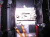
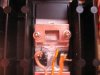
Been asked by a fellow AK member to save this 1980 from doorstop status. Poor thing was used and abused during its past and tore up internally pretty badly. If ever a case were to be made to never turn on a piece of acquired gear without first pulling the covers this would fit the bill. Notice the burned/cut output wires left bare against the heat sinks.
-Lee
 

Attachments

  • 1980output1 (600 x 450).jpg
    1980output1 (600 x 450).jpg
    56.1 KB · Views: 523
  • 1980output2 (600 x 450).jpg
    1980output2 (600 x 450).jpg
    44.6 KB · Views: 461
Register to hide this ad
Ouch... thats going to need some work. Are you going to find NOS replacement outputs or are you going to do the EchoWars mod and sub in the ON-Semi devices?
 
Already have the EW recommended replacement outputs in hand. Repaired the busted off leads to the st4 diode and sealed per MTF's tutorial. Today's entertainment will be the rebuild of the regulator board once I figure out the safest way to flip this lightweight over on the bench.
 
Stand it on it's left side, use thin ply/wood to adjust the height differential between the chassis and the heat sink fins. Of course the heat sink has to be in place, then desolder the 6 wire wrapped pins and you'll be able to pivot it out almost 90 degrees.

and I stand it all on a 11 inch diameter lazy susan turntable sandwiched between two pieces of plywood ~ 1' x 2'

oh well, I can't have ALL the fun... :sigh:

ran through one not too long ago that had evidence of multiple powerline shorts around the AC socket, a sickening amount of that white-grey ash/plating in the vicinity over EVERYTHING.... the things someone (very unskilled in soldering) did to compensate, rather than just replacing the socket was disheartening.
 
Last edited:
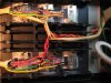
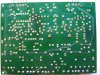
Nothing like picking up the pieces. Rebuilt the outputs and moved on to check the driver board. Oopsie, looks like madman soldering iron wielder been here too. Disconnected parts, lifted traces you name it we gots it. Sigh. Also took a peek at the regulator board using Marks method of safely getting to it and have damage to repair there too. Oh well, one task at a time.
 

Attachments

  • repaired outputs.jpg
    repaired outputs.jpg
    76.8 KB · Views: 390
  • missing parts.jpg
    missing parts.jpg
    89.8 KB · Views: 285
  • moremissingparts.jpg
    moremissingparts.jpg
    66.2 KB · Views: 312
  • wanderingtransistors.jpg
    wanderingtransistors.jpg
    72.2 KB · Views: 361
Are those COINS (dimes) between the output transistors and the OLD transistor hold downs?:sigh:

AND you reused the old insulators, which puts a square hole in exactly the wrong place... well with NO clamping force it MIGHT not short. But are those transistors going to overheat?

edited: it ain't a pretty job...
 
Last edited:
It looks like you are using the factory transistor hold downs. I had mine apart for cleaning and adding new thermal grease. With the different dimensions of the ON-Semi outputs, it would seem to me that the factory sheet metal retainers for the outputs would flex and not apply even pressure to the ON-Semis, applying pressure at the edges and not in the middle. ...But maybe I am missing something. Maybe Mark will chime in soon and correct me.

EDIT... it seems that Mark and I were posting at the same time, as his response is right above mine. I didn't notice the coins when I wrote my response the first time, but now after enlarging the pics, I see $0.60. I assume that is to correct the 'even pressure' issue.

it's not flexing, the on-semi's are THINNER than the originals and I'll bet his screws were bottoming out in the holes and the transistors were still loose. Flexing is also a factor but I'll bet it wasn't included in his figuring. The original transistors had a notch that encircled the screw on 3 of 4 sides.
 
On the other hand the old mounts did hold the transistors in place so I could rewire the assembly until I can get the new aluminum pieces cut out (have the aluminum) but not yet had time to drive the 40 miles each way to use the bandsaw and drill press to finish them off. The dimes were used as spacers to locate the transistors so that the mounting screws would NOT bottom out in the heatsinks while I was redoing the wiring. All six mounting pads were checked. It will be a long time before any power is applied, I was hoping more for a quick check of wiring rather than a bomb blast.
 
it's not flexing, the on-semi's are THINNER than the originals and I'll bet his screws were bottoming out in the holes --snip--

The ten cent spacers make more sense now.

Couldn't you PM one of the members that made the spacers for EchoWars? ...or do we have another source now? It almost seems that there would be an easier way for you than re-inventing the wheel and having to goto all the trouble of cutting aluminum, especially if someone already has some spacers made or has been through this before.
 
EchoWars didn't reuse the sheet metal retainers or use spacers, they were replaced with bar clamps.


That would be me. Although EW's sources (2 of them) had access to machine shops. I have made the clamps before, and Overundr1 and I have PM'd back and forth on the details.

I quoted him a ridiculously low (for me?) price (as a favor, not a service) versus what a machine shop would charge, I have the 1/4 x 1/2 aluminum bar stock, and drilling jigs, it would have to be accurately cut on a 10" table saw with a plywood/soft metal blade, and then drilled. It would definitely kill half a day by the time it was finished. 24 bucks for materials and an afternoon of my time? ($2 ea x 12 hold downs + shipping)

he would also need keystone 4661 micas 24 = 2 x 12 x $0.28 ea at mouser
and 24 M3 x 0.5 x 18mm screws, new lock washer and uncorroded washer.

www.fastener-express.com

3mm Metric Flat Washers Plated Qty. 50 31452 $2.10
3mm Lock Washers Metric Plated Qty. 50 31483 $0.95
M3 x .5 x 18mm Pan Phillips Machine Screws A2 Stainless Steel Qty. 50 31570 $3.31

EchoWars before wiring:
attachment.php


mine after wiring:
attachment.php
 
Last edited:
Mark,
Yes you did and I both appreciate the offer and with your approval may still take you up on the brackets. However, I did source the .250 inch aluminum, have the dimensional pattern from Glenn's posts and a friend with the tools to cut them out. It's not about having you or anyone else make the mounts, its more about learning to be self sufficient and not bust on the few techs who take more than a little of their time to support and teach others. I suppose I should have detailed why I set up the temporary mounting system. I was more interested in showing the re-wire, the solid solder joints, the straight wire runs and maybe a quick check to ensure I followed the pattern correctly.
-Lee
 
Last edited:
EchoWars didn't reuse the sheet metal retainers or use spacers, they were replaced with bar clamps. ---snip---

Sorry, I meant to say metal bars. I knew what I wanted to say, I just used the wrong terminology. Shame on me for not proofreading that post. :bash:
 
Had to do this last year for a 1980. Had a machinist friend punch out 100 bar brackets for me. Just sitting in a box and I'm sure I'll never use them all. PM me if you need some.
 
Thanks Mike. Found out how much fun it is to make those tie down brackets by hand without the proper tools. Once they arrive I will finish the board with new mica insulator pads, stainless hardware and pretty up the wiring. In the mean time as I work through the amp driver board I need a check on a couple of transistor subs that I need to replace--- please correct me if I did a poor cross reference. All available at Mouser.

A939A (b.c.e) substitute mje350 (e,c,b)
C2071 (b,c,e) substitute mje340 (e,c,b) tested good wanted matched pair
A968 (b,c,e) substitute 2sa1837 (b,c,e) mica insulator was missing
C2238 (b,c,e) substitute 2sc4793 (b,c,e) tested good ditto

Thanks,
-Lee
 
A939A -> KSA1381E
C2071 -> KSC3503E

The 2SA1837 & 2SC4793 are OK, and won't need an insulator.
 
I used mje15032, mje15033.

EW: Think 30mhz vs 100mhz makes much of a difference?

with the 35 MHz outputs:
63-mjl4302ag pnp TO-3P/TO-264 bce 350V 15/30A 230W 35mhz 50-250hfe $6.25
863-mjl4281ag npn TO-3P/TO-264 bce 350V 15/30A 230W 35mhz 50-250hfe $6.25
 
I used mje15032, mje15033.

EW: Think 30mhz vs 100mhz makes much of a difference?

with the 35 MHz outputs:
63-mjl4302ag pnp TO-3P/TO-264 bce 350V 15/30A 230W 35mhz 50-250hfe $6.25
863-mjl4281ag npn TO-3P/TO-264 bce 350V 15/30A 230W 35mhz 50-250hfe $6.25

Sorry, didn't express myself clearly:


original driver is A968 is 100mhz

one substitute driver; 2sa1837 is 100mhz
other substitute driver; mje15033 is 30 mhz

original output transistors are 2sb706 at 15 MHz
substitute output is mjl4302ag 35 MHz

using a 30mhz driver versus using a 100 mhz driver


for a 35 mhz output transistor
that replaced the original 15 mhz output transistor.

so:
EW: Think 30mhz vs 100mhz makes much of a difference?

It didn't SEEM to make a difference in the one I did already...
 
Back
Top Bottom