• The move to the new server is done. There are some software and database maintenance updates in process. This has us passing the hat around to help out. We appreciate any donations. Seriously, even a dollar helps. The payment page may be found here - https://www.audiokarma.org/support.html

Resurrecting 500-C SN55172 (was 500-C funeral)

audiodon

Addicted Member
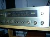
This is the story of Fisher 500-C #55172R.

What goes around comes around.

In the late winter of 2006, I purchased a 500-C off ebay. This Fisher was sold out of Amherst, Massachusetts, so I elected to pick it up, with Amherst being about a hour and a half west of where I worked at the time.
While I was there, the seller said, "I have another one that you can also buy, but it has no tubes and has not been turned on in years.

I bought it.

This is the story of that second Fisher 500-C, serial #55172R.
That one was dirty, with somewhat rusted transformers and a very dusty chassis. It had seen quite a bit of use too, having been used in a store, and the tube sockets were a dark brown color.

It spent two years in my garage.
When I finally had the time, and the inclination, and had collected some tubes, I brought it out, cleaned the chassis, removed and cleaned the front panel and dial glass, popped in some tubes and brought it up on a variac. Lo and behold it worked . . . and quite well, I might add. I'd used some marginal tubes but it didn't seem to mind. I did use my favorite line stage preamp tubes. Also, I threw in a quad of EH 7591s from an amp I'd bought from motorstereo.

So, I gave it new coupling caps, updated the multiplexer, and did everything but replace the electrolytic caps, including replacing the rectifier, first stage filter caps and replacing the diodes with hexfreds. I used a quad of K42Y PIO caps in the output. I also painted rustoleum black on the transformers.

Then I brought it into the shop of my favorite local ebay flipper with a pair of speakers and set it up for demonstration and sale. I set the price low because the restoration was incomplete and the tubes weren't the best.

Lo and behold the receiver garnered a lot of attention, including from AK'er gigbyt. So, I sold it to him, but with him being someone who would know the difference and deserved a fully restored amp, I told him I'd have to replace the electrolytic caps, and burn it in fully. I also put in some stronger tubes, knowing I'd make almost no money, but someone would put this amp that thrived on abuse to good use.

This was in the Winter of 2010. At the time I told him I don't don't work on gear in the summer.

In the late Spring, gigbyt came back and stated that the amp made noise sometimes, and only intermittently, on his Klipshorns. I told him that I don't work on gear in the summer but I had an integrated that was almost done he could use if he dropped it off.

Something was wrong with the first integrated gigbyt took so I had him take a second one.

I do have a picture of 500-C before I restored it, but it's on another computer and I'll have to add it later.

We can call the problem with the 500-C tube farting. It would be dead silent, and then there'd be some noise that was untraceable. After it sat for five months because it was not my work season, I was able to track down this difficult problem with help from AK'er sgmlaw.

So, gigbyt got his amp back, but his confidence had been shaken and he decided to sell it. He sold it on AK and had it professionally packed and shipped. That's where the trouble began.
http://www.audiokarma.org/forums/showthread.php?t=329919

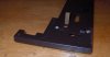
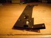
Well, I've got it back on my workbench now, but with the holidays I won't get to it for another week. Here's some damage pictures.
 

Attachments

  • DSCN3993.jpg
    DSCN3993.jpg
    49.4 KB · Views: 115
  • DSCN3994.jpg
    DSCN3994.jpg
    62.2 KB · Views: 87
  • DSCN3995.jpg
    DSCN3995.jpg
    65.5 KB · Views: 98
  • DSCN3996.jpg
    DSCN3996.jpg
    77.8 KB · Views: 133
  • DSCN3997.jpg
    DSCN3997.jpg
    61 KB · Views: 134
  • DSCN4011.jpg
    DSCN4011.jpg
    85.2 KB · Views: 146
Last edited:
Register to hide this ad
Here are some more damage photos.

This unit has come back to its home. There is hope. It's like a damaged car being brought into a body shop.
 

Attachments

  • DSCN3998.jpg
    DSCN3998.jpg
    87.7 KB · Views: 90
  • DSCN4012.jpg
    DSCN4012.jpg
    65.9 KB · Views: 81
  • DSCN4005.jpg
    DSCN4005.jpg
    88.3 KB · Views: 91
That day was filled with so much hope and excitement driving to Fedex to pick it up from their facility. :yippy:

My girlfriend says "What are you doing up at 7am!?" I answer "Going to pick up my mint 100% restored 500c by Audiodon from Audio Karma!" She glances over at me and rolls her eyes at my excitement as usual...:rolleyes:

When I opened the box, I'm sure Avery Fisher himself rolled over in his grave at the sight of the poor 500c just thrown into a box with a little bubblewrap and nothing else.... :tears:

I do not think there's a better guy on AK to attempt to being this 500c back to all it's glory and tell the story along the way! :yes:
 
He should be able to. remember the neglected 400 he did last year???? I inherited it's cousin. The 500 should be singing soon with a minimum of fuss. Parts are another story, Unless he's got donors out in the shed. Wonder if the subframe for a 400 is the same???? One from an 800 should work.
 
The 500-C features a subframe with two cutout holes . . . one for the signal strength indicator and one for the stereo beacon. Unfortunately, a replacement with a 400 or 500-B subframe would not do it unless I had access to a hole punch to cut out a single hole. I'm going to attempt to straighten it before sacrificing a unit.
 
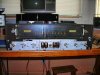
I found some pictures of the Fisher before I started the original restoration. I've decided to make this thread complete.
First: What it looked like.
Second: First restoration.
Third: Body Shoppe restoration and the sacrifices made to get it going.

This one had slightly rusted transformers, a lot of time on it, and was bone stock.
 

Attachments

  • Fscn0191.jpg
    Fscn0191.jpg
    93.9 KB · Views: 105
  • Dscn0187.jpg
    Dscn0187.jpg
    103.3 KB · Views: 105
Now I'd like to catalog the initial restoration.
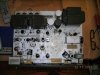
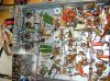
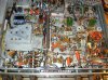
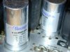
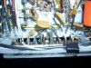
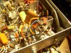
These pictures will show that all electrolytics, can caps, diodes, major coupling caps, and some mpx caps were replaced.
 

Attachments

  • chassisfinished2.jpg
    chassisfinished2.jpg
    149.9 KB · Views: 89
  • chassisfinished.jpg
    chassisfinished.jpg
    150.3 KB · Views: 87
  • newcaps.jpg
    newcaps.jpg
    65.6 KB · Views: 83
  • Fscn0189.jpg
    Fscn0189.jpg
    86.6 KB · Views: 82
Ok, enough history. Now on to the resurrection.
First step was to get the brown front panel off and assess the damage.
I took off the anodized front panel and then disconnected the brown panel behind it. Here's what I found:
 

Attachments

  • fp.jpg
    fp.jpg
    17.2 KB · Views: 94
  • fpleftside.jpg
    fpleftside.jpg
    31.6 KB · Views: 99
  • fprightside.jpg
    fprightside.jpg
    55.3 KB · Views: 103
Thanks Dadbar. Happy New Year to you too.

First up: Switches.
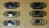
I had a few kicking around and I had a donor amp that had a couple in it, so I spent an evening cleaning up and testing switches. When I was done, I had six switches . . . three with a crimson reveal, and three with a brass reveal. The reveal is what you see on the part of the switch when the switch is (typically down) in one position or the other. It's not the part that sticks out. It's the other part that's flush with the back of the switch. In the second picture, the ones on the left are crimson reveal (or call it what you want, but they're not black). The ones on the right are brass reveal.

Well, I needed four with the same reveal because I certainly would know that I'd rigged it incorrectly.

So, I had to strip a switch from a 500-B chassis with no transformers that I had saved for a dream project someday. Actually, I stripped all the switches.

So, I've put them in and here are the after pictures.

It's surprising how long it takes to do something correctly.

To clean and check the switches and clean all the stray wires, resistors, caps and residue off the switches took a whole evening.

To put the switches in took a good long time too because it's not exactly a new build. You know . . . extend this lead, reroute that wire, clean the hairy insulation off this . . .
But the results are acceptable.
 

Attachments

  • newswitches_4_0111.jpg
    newswitches_4_0111.jpg
    100.7 KB · Views: 85
  • newswitches_2_0111.jpg
    newswitches_2_0111.jpg
    78.9 KB · Views: 78
  • switchreveals.jpg
    switchreveals.jpg
    55.9 KB · Views: 93
  • switch2clean.jpg
    switch2clean.jpg
    74.9 KB · Views: 75
  • newswitches_3_0111.jpg
    newswitches_3_0111.jpg
    93.5 KB · Views: 91
Last edited:
Well everybody,
I've decided to do the rest of the update the easy way.
Rather than taking the time to bend everything and hope for the best, I raided parts off a 500-C I had in the garage.

Next up: Replacement front panel and front bezel:

Last year I bought a project 500-C off AK'er DennyDog. People were threatening to strip it for the iron so I bought it as a restoration project. It was pretty dirty, as you can see from the first photo.
The serial number is in the same range.
So, I removed the front panel and the brown panel behind it.

Now I still think I want to keep this donor 500-C and will continue looking for a carcass to get a bezel, front panel, some knobs, and the dial glass from. Though this DennyDog 500-C was stripped of every 12AX7 and 7591 tube, the other tubes are original Fishers and were in the socket's pretty tight. Testing a socket, it had serious grip which, to my mind, means that this one was used, stopped working, got thrown into the cellar, and sat for years, but it's still a likely candidate for restoration. It's also bone stock. I don't think the bottom cover has ever been off.

My next step on the shipping damaged 500-C was to fix or replace the bass pot before putting the front bezel, dial glass, front panel, and new knobs on.
The bass pot is made up of two ganged pots in one assembly, connected to a PEC module with equalization circuitry inside.
Both bass and treble are matching dual 500k pots.

Looking at my Fisher 400 parts chassis, I realized that the orientation of the tone control pots on the 400 is different physically than the pots on the 500. They also have a different part number on the parts list. Each tone control pot is two ganged and attached rotary pots with each having three leads next to each other and another lead on the other side 180 degrees away that remains unused. On the Fisher 400, the three leads on the inner pot are 180 degrees away from the three leads on the outer pot, and the PECs are oriented differently. On the 500-C, the three leads of both pots are on the same side and the single unused lead of each of the two ganged pots is on the same side.

My trusty switch donor 500-B, though, had tone control pots that were the same orientation as the pots in the 500-C. So, I snipped out the bass pot from the 500-B as shown in the picture where you see a unit with no switches. To be continued . . .
 

Attachments

  • DSCN0066.jpg
    DSCN0066.jpg
    53 KB · Views: 70
  • DSCN0068.jpg
    DSCN0068.jpg
    86.6 KB · Views: 56
  • DSCN0071.jpg
    DSCN0071.jpg
    74.8 KB · Views: 62
  • DSCN0073.jpg
    DSCN0073.jpg
    60.4 KB · Views: 68
Last edited:
The first picture is of the damaged bass pot in the 500-C I'm fixing. What happened was that the front stalk of the tone control got pushed back, breaking the clamping of the front bass pot and breaking the phenolic that held one channel of the bass pot together. So, squeezing it back together, though I tried it and you can see my attempt here, did not fix the pot. With the phenolic broken, the wiper did not see continuity through its 270 degree swing. I guess that the wiper piece got bent when the phenolic it was attached to got split in half. Therefore only a replacement part would do. So, I diagrammed how each lead was wired for later reference.

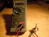
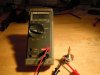
Back to the 500-B I'd raided switches from. I snipped out and took off the bass pot, cleaned it with my trusty contact cleaner, ran it back and forth 25+ times and tested it on the meter. One wiper went from about 20 ohms to 470k. The other wiper went from about 168k to 470k. So, I cleaned it again. No better. Next I tried tightening the clamps on the bad pot. No better.

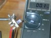
Then, after checking the schematic and verifying that the bass and treble pots on a 500-B are the same pot, as well as similar in function to the pots in the 500-C, I snipped out the treble part, cleaned all the wires off it and tested it. That one ran from about 12 ohms to 512k ohms on both sides, as seen in the second and third pictures. So I cleaned it well with deoxit and gave it 50 swipes left to right, ran each channel of the pot separate from each other and then put them together and tested it again. It worked like a champ.

When I went to install it, I realized that yet another example of hidden damage was that the chassis where it supports the bass control was bent. You can kind of see it in the first picture if you look closely at the bottom (near the top of the receiver's chassis). The stalk stuck out sideways when installed properly and there'd be no way I could install a straight front panel over the bent stalk and have it look right. So, I removed the new bass pot again before soldering the six contacts in. Using a hole punch stuck through the hole, I bent the chassis back into position.

Next I put the bass pot back in, bolted it in with the retainer bolt, and slipped the front panel on. The front panel did allow the pot stalk through, but it wasn't perfect. I did the final bending with the bass pot in place by applying equal pressure to the stalk with one hand (pull) and to the two pots with the left hand (push) at the same time. It worked fine. Then I soldered in the six leads from the diagram I'd drawn of what lead goes where, plus I reconnected the PEC's ground lead (pin 1), which I'd had to remove to withdraw the original pot. Another task completed.
 

Attachments

  • DSCN4019.jpg
    DSCN4019.jpg
    89.4 KB · Views: 49
  • DSCN0075.jpg
    DSCN0075.jpg
    61.7 KB · Views: 46
  • DSCN0074.jpg
    DSCN0074.jpg
    61.6 KB · Views: 46
  • DSCN4015.jpg
    DSCN4015.jpg
    114.3 KB · Views: 56
Now I'll tell you how I fixed the tuner flywheel, reattached the front panel and made everything look nice.

Earlier, before I removed the original bent front brown bezel from the damaged 500-C, I'd diagrammed how the dial string went. Interestingly the Fisher 400 documentation has a diagram about how to restring the dial string, but the pulley arrangement is different on the 400, on the 500-B and on the 500-C from each other. Therefore, after checking my 500-C documentation, I realized it had no equivalent 500-C tuning dial restring instructions. So, I diagrammed it myself.

I'd pulled a tuner flywheel holder and flywheel off the donor Fisher 400. Well, I ended up just bending the flywheel holder already on the 500-C until it was vertical according to my vertical level.
I'd thought that the 500-C's flywheel stalk was bent. So, I used the 400's flywheel stalk but it was about 3/4 of an inch too short and the positions to put the C-clamps to hold it in place didn't line up correctly with the 500-C. I had to raid the flywheel from DennyDog's old 500-C, which had a broken dial string anyway. Fortunately the height of the vertical flywheel holder was not an issue since I didn't use the one from the 400, but bent the one from the damaged 500-C back into position. So, I strung the three loops that go around the 500-C's tuning flywheel around the replacement flywheel, used the plastic grommets but did not put the C-clamps in yet to hold the bezel into place. Then I soldered the wires on the left side just below the switch for speaker set 1/speaker set 2/speaker set 1&2/earphones is. You can see the soldering and shrinkwrap in figure one. These wires power the festoon (fuse-like looking) lamps on the sides of the dial glass.

I also attached the wires on the other side that go from the stereo beacon light to the festoons and soldered and shrinkwrapped them into place. Then I screwed the bezel into place using the six self-tapping screws similar to the ones that hold the chassis bottom in place, making sure the bezel cleared all the knobs, and that the tuning dial indicator was in its proper place before bolting it back in.

Next, I restrung the dial string over the pulleys and I was lucky not to break it. I put it all together and realized that in one spot going to the tuning wheel the string was mis-routed and it would turn, but would rub and fray, eventually breaking. So, I had to unscrew the bezel again, pull the tuning wheel stalk out of the vertical backing guide to release the pressure from the dial string, reroute the dial string and reassemble the assembly again. This time I did put the c-clamps in the slots it goes on the tuning flywheel shaft both behind and in front of the bezel. The dial string worked freely but is tight. I also aligned the tuning dial while proper station. They tell you to turn the tuner wheel maximum counterclockwise and align the dial string indicator with about where 88 will be on the dial glass. I did that.

The front panel cleaned up pretty well with 1 part ammonia to four parts water. I immersed it in the solution in our flat-bottomed slop sink for about two minutes, then wiped it with a white 3M cleaning pad (lightly). After rinsing it with clear water and blotting it dry, I noticed a couple of drops of some dried liquid still on it so I attacked them with an old toothbrush with the ammonia/water solution again, being careful of the lettering and rinsed it all again.

For the dial glass, I always use windex. On the front, where there's no painted lettering or numbering, I wipe vigorously. On the rear, where the lettering and numbering is painted on, I blot where the paint is, and wipe more vigorously where it isn't. The Fisher paint is more robust than some others I've seen.

Well anyway, the front panel all came together upon reassembly. I also cleaned the new knobs I had to raid from DennyDog's 500-C in that ammonia/water solution with a toothbrush, brushing front to back to follow the plastic knurling. The knobs I raided had no knob brights and I had just a couple of used vintage ones left of a comparable patina.

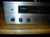
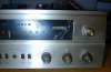
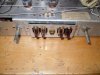
The pictures show the results of the effort on restoring the front of the 500-C.
 

Attachments

  • DSCN4020.jpg
    DSCN4020.jpg
    64.2 KB · Views: 53
  • DSCN4022.jpg
    DSCN4022.jpg
    65.4 KB · Views: 51
  • DSCN4025.jpg
    DSCN4025.jpg
    56.2 KB · Views: 52
  • DSCN4026.jpg
    DSCN4026.jpg
    56.6 KB · Views: 48
  • DSCN4024.jpg
    DSCN4024.jpg
    61.5 KB · Views: 78
Next: Replacing the phenolics where the speaker assemblies attach at the back of the unit:
The speaker connector phenolics are riveted in. I had to use a drill to break out the rivets. I did drill them out on the speaker connectors, figuring that I'd bolt the new phenolics in.

I'd bought a pair of four speaker connector phenolics from Jim McShane for a Citation project that I haven't started yet. So, I decided to use them on the Fisher 500-C. Fortunately, the designations are silk-screened onto the chassis and not onto the phenolics, as they are on some other Fishers. So, I didn't have to think of using a label maker to mark terminals.
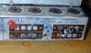
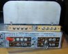
Here's a picture of the speaker connector phenolics after I drilled them out with only the neutral wires from the output transformer still attached.

I marked the color code of the speaker connector wires to each phenolic. They come from the speaker 1/2/earphone switch at the front panel and are inside a coiled shield soldered to the sidewall of the chassis in multiple places. That is, the speaker1, speaker2 and common taps come from through the shield and the common tap also connects to a neutral wire that comes from the output transformer to each respective push-pull pair's common connection.

So, the common for the left, which is jumpered between the com pair 1 and com pair 2 on each phenolic, comes from one output transformer and the same is also true of the common for the other output transformer going to its respective common terminal. That's in addition to the common connection that goes through the coiled metal shield soldered to the sidewall.

I diagrammed the connections before snipping them from the phenolics and drilling out the rivets. Then I had to unsolder the shield containing the speaker pair wires because the leads were too short to redo without removing them, doing the soldering of the leads, and resoldering the shield. I needed about an extra half-inch of play to get the shortest lead back in.

I put the two new phenolics in, held them in place with a pair of throwaway chopsticks, soldered in all the connections, and had the unit ready to turn on. Unfortunately, I didn't have any small bolts with nuts and lock washers so for now some beveled chopsticks are holding the phenolics in place and will be until I heal from some minor surgery that'll keep me housebound for a week.

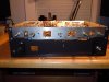
After completing those connections, I put the output tubes back in, connected some screw-terminal to Banana adapters for speaker leads, connected the speakers, connected my digital player in the workroom, put on the bottom panel, flipped the unit over, verified that the phenolics that weren't bolted in were not shorting to the chassis, and plugged the Fisher 500-C's AC into the variac. I set the voltage to 60 volts and turned on the Fisher 500-C in an attempt at resurrection after it had already had a funeral.
 

Attachments

  • DSCN0081.jpg
    DSCN0081.jpg
    73.3 KB · Views: 97
Last edited:
You keep coming back for 2nd's after an hour or so, don't ya!!!

Good Job Don! Looks like this one is gonna have a Good 3rd lease on Life, provided it doesn't come close to The DUNDERHEADS @ FedEx, USPS, UPS.

Larry
 
Yes. I had minor surgery and wasn't able to do much but sit. So, since I could sit at a computer, time gave me an excuse to write.
You know how these things go Larry. Proper posting and storytelling is time-consuming.
I'd done a number of things before the surgery and took pictures along the way to remind myself what I'd done.
Then I did a brain and image dump over a number of posts.
Now there's no heavy lifting for a while so the unit will sit.
 
"Professionally packed and shipped," eh? Was it perhaps handled by this creature?

gorilla1.jpg


gorilla2.jpg
 
Back
Top Bottom