• The move to the new server is done. There are some software and database maintenance updates in process. This has us passing the hat around to help out. We appreciate any donations. Seriously, even a dollar helps. The payment page may be found here - https://www.audiokarma.org/support.html

Sony TA-4650 (Recap Work-log)

Snerp

I solder while you sleep...
I decided to delete my old thread and start new. My few questions that I originally asked were answered. This is a recap work-log.

I was tinkering with the receiver last night. I got a new digital mulitmeter yesterday. The bias will range from 49-54mV. I think I want to recap everything. I don't think I will be keeping this, but I'm not done playing with it yet. I like the act of the project. While the end product is always fun, the actual work is where I get my kicks.

I have been looking at Tim5's post HERE. Everything is pretty straight forward, except the 4700uF Cap and the Omron relay he installed.

Is THIS a suitable replacement for the cap? What relay would I need? Thanks in advance.

:EDIT:

I have answered my own question after an hour or so of digging. Looks like I will need a screw cap capacitor for the bit 4700uF/50V replacements. Now I just have to figure out exactly which one.
 

Attachments
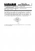
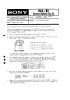
  • Service Bulletin.jpg
    Service Bulletin.jpg
    1.9 KB · Views: 146
Last edited:
Register to hide this ad
I think I have this figured out. I just have two questions. Will two of THESE or THESE work as a replacement for the 4700uF/50V? Will a 3.3uF/100V be an acceptable replacement for a 3.3uF/25V?

Other than that, here's my buy list. Just in case someone in the future is looking to do a recap.

:EDIT:

I revised my buy list. See post #9 for final buy list.
 
Last edited:
4700uF/50V - x2 871-B41456B8478M - Pending on above question

Yes you could use that one.

If you're searching caps keep the microfarad (uF) as original, for the volts you can choose a higher value, but don't go lower.

For the relay you could use this one, 653-MY4-02DC24, but the pins are too width, you can use a multi-tool to make them smaller.
 
Last edited:

Does voltage matter at all? I know it doesn't with speakers. Just as long as it's above the orginal voltage.

I popped my fuses last night and had to MacGyver some. I don't want to explain how I managed this, because it was an extremely stupid move. everything is fine other than the ugly fuses. When you see pics of my power board, you will know what the Frankenstein tape job is.


:EDIT:
Perfect! Thanks guys
 
Last edited:
I popped my fuses last night and had to MacGyver some.

Don't MacGyver to much, it is very easy to kill the V-fets, if not already, there precious, very hard to source, if even......

Change the trimpots to, choose multi-turn, 1Kohm should work or as original 2.2Kohm, this is important!!

Lower the Bias to 30mV per channel.

Replace the thermal grease of the V-fets, keep the source and gate free from the grease, make sure that the screws stay clean to as they are connected to the drain or are the drain.
Best is to measure the resistance between contact points V-fet and the board, there should be close to none resistance.

Take a look at this post, it was very helpful to me: http://www.audiokarma.org/forums/showthread.php?t=244646

Read as much as you can about the V-fet amps, lots of info to be found @ audiokarma.
 

Attachments

  • ModificatiesVfetampsony.jpg
    ModificatiesVfetampsony.jpg
    76.4 KB · Views: 137
Don't MacGyver to much, it is very easy to kill the V-fets, if not already, there precious, very hard to source, if even......

Change the trimpots to, choose multi-turn, 1Kohm should work or as original 2.2Kohm, this is important!!

Lower the Bias to 30mV per channel.

Replace the thermal grease of the V-fets, keep the source and gate free from the grease, make sure that the screws stay clean to as they are connected to the drain or are the drain.
Best is to measure the resistance between contact points V-fet and the board, there should be close to none resistance.

Take a look at this post, it was very helpful to me: http://www.audiokarma.org/forums/showthread.php?t=244646

Read as much as you can about the V-fet amps, lots of info to be found @ audiokarma.

Thank you for the link. That will be very helpful. I have already replaced the diodes and the thermal interface compound. I have worked on computers for years now and treated the vfets much as I would a CPU. I used a high performance grease that isn't conductive or capacitive.

Since voltage doesn't matter I will be rebuilding my buy list. That way I can stick to Panasonic's FM series.

The vfets seem like they are still working. I was still getting bias readings. I'll have to test it more tonight. The only MacGyver move was turning a 2A slow blow into a leaded fuse with copper solder wick and electrical tape. It's not like I bridged it with a paperclip. :D
 
How to test V-fets with multimeter :yes:

Excellent! I will be testing them within the hour. Thank you for all the help Tim5. I really appreciate it.

My buy list is found [REMOVED] (was not my final list). I think I'm going to get transistors while I'm at it. I switched out the Panasonic FCs for Nichicon PWs. When it comes down to it what's $5 when I'm already spending $40+.

I will probably pick up a few extras, just in case...again, what's another $5 :rolleyes:
 
Last edited:
Originally Posted by Tim5
Quote:
Originally Posted by Snerp
I was reading over your transistor list and I have a question. You have listed:

"Q202,252,204,254: 2SA705 = BC556B"

So does that mean any of THESE transistors would work? What qualities am I looking for in a transistor? Is one of those 5 better than the others and why?

Another item on the list has the note "match those by HFE, for offset". What does this mean and how do I do it?

Thanks so much for your help. The good news is I learn quick and you'll only have to hold my hand through the one project.

-Garret
Yes they would all work, take the cheapest, they are al brand items, the difference would be the Hfe, in this case this don't matter.
For matching you need buy more than needed transistors, in this case lets say 30 pieces.


Transistor matching Hfe:

The easy way: using a DMM
This is the easiest, fastest and most simple way: use a digital multi meter (DMM) that sports a hFE mode. Just put the transistor to the supplied socket, select hFE mode and read the value on the display. The DMM calculates the hFE for IB being a fraction of a mA but that's precise enough for most applications.

deviations between DMMs
most probable reasons:

-different loaded batteries
-different current measure points

How close to match the hFE values
5 is almost perfect. 10 to 20 is just fine. Probably you'll have to accept larger deviations (about 30), even with large quantities from one shop, from one manufacturer and one manufacturing batch matches are not guaranteed

I googled that info

Offset? read Echowars post:
http://www.audiokarma.org/forums/showthread.php?t=5634&highlight=offset

But it is not really necessary to swap transistors if they arrant defective.

If you want to learn how to check transistors (BJT), this a nice post also by Echowars:
http://www.audiokarma.org/forums/showthread.php?t=43186&highlight=transistor+tester

Please keep in mind I'm no expert on these matters, I do this hobby wise, and started just like you, two years ago
 
Last edited:
I've decided to stick with my purchase list. I'll consider transistor replacement after I replace all the caps and only if it's necessary. Come payday, I'll order everything and get this rolling.

I am also planning on breaking everything down and creating an all inclusive TA-450 guide, with pictures, once I'm done. There is a TON of info on these receivers, but it's found within 20+ threads. Hopefully a one stop thread will help someone in the future.
 
I ordered everything this evening. I'm guessing I will be receiving the package early next week. Time to get the soldering iron and DMM out! :D
 
I received my order from Mouser. Looks like everything is here. The packaging is awesome and everything is very well labeled. I'm impressed.

The iron is hot...time to dig in.
 
I brought this project back to life. My TT project has stalled out and I needed something to do. I had to do some major jury rigging on the 4700uf caps. They were about 3/8" too tall and 1/4" too skinny. This was the orginal reason I shelved this one. I was a tad grumpy that $30 worth of caps were all wrong.

In my boredom, I fixed the problem, and now I'm soldering away. I have got all the caps replaced on the board with bias adjustment. Two of the same value were leaking. I think they were the 220uf 10v at the base there.

Basically, I've a few more caps, the relay, and the speaker inputs.
 
Something I've seen done is manufacture a board for snap in or solder tab caps, then attach the wiring to that. It makes your selection of available caps much larger.
 
Something I've seen done is manufacture a board for snap in or solder tab caps, then attach the wiring to that. It makes your selection of available caps much larger.

Well, the screws were a red hair (from you know where) off. I drilled out the PCB and they were good to go. I then wrapped the caps with 1/4" rubber mat and then taped them up with kapton tape. They fit snuggly into the bracket.

Pretty jankie, but it works.
 
Turns out I missed a cap when ordering. $.28 for the cap and $6 s&h doesn't work for me. Since I was thinking about it anyway, I'm going to go ahead and replace the RCA jacks with some color coded gold plated Switchcraft jacks. I'll replace everything but the XLR and the 4 RCAs on that pannel.

It's a bit overboard, but I'm having fun with it. I doubt I'll get my money out of it. Someone is asking $250+s&h for a completely stock, untested 4650 on everyone's favorite auction site...you never know. He'll never get it, but maybe I could. Maybe I'll keep it. Anyway, lots of fun the past few nights.
 
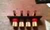
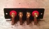
The speaker inputs on panel "B" are finished. It was quite the process. I think they turned out nice. After removing the old terminals, I sanded and filled the holes. Sanded the panel face with 1500, and drilled for the post. The colored plastic was wider at the base, so I had to trim it up a bit.

I ordered the RCA Phono Jacks. They should be here by next weekend . Hopefully I can get it all buttoned up and done without too much hassle.

attachment.php

attachment.php

attachment.php

attachment.php

attachment.php
 

Attachments

  • IMAG0359.jpg
    IMAG0359.jpg
    62.7 KB · Views: 121
  • IMAG0358.jpg
    IMAG0358.jpg
    52.9 KB · Views: 122
  • IMAG0363.jpg
    IMAG0363.jpg
    49.3 KB · Views: 120
  • IMAG0360.jpg
    IMAG0360.jpg
    60.8 KB · Views: 117
  • IMAG0361.jpg
    IMAG0361.jpg
    59.8 KB · Views: 119
My jacks came in. They look very nice. I'll be installing them in the next few days. I installed my last cap, set my bias and then gave it a listening test. No right channel. I freaked out. I was sick over it. I really thought I had just crafted a boat anchor.

Messed with it every way possible...nothing. I was still getting a bais reading, so I started to go through everything. It took awhile, but I found the thinnest bridged joint on the relay I have ever seen. A very small part of the PCB was warn between the two joints and solder flowed over on the exposed path.

She's sounding beautiful! Absolutely beautiful! A farcry from the flat, non-dynamic receiver I started with. Something must have been way out of spec because I'm blown away.

I'll post pictures when I get the phono Jack's installed.

:EDIT:

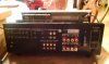
I couldn't stand it and I got started on the RCA jacks. Here's a pic!

attachment.php
 

Attachments

  • IMAG0386.jpg
    IMAG0386.jpg
    61.3 KB · Views: 111
Last edited:
Back
Top Bottom