• The move to the new server is done. There are some software and database maintenance updates in process. This has us passing the hat around to help out. We appreciate any donations. Seriously, even a dollar helps. The payment page may be found here - https://www.audiokarma.org/support.html

H/K 330C Restoration

I'm starting a thread which will show my progress on restoring my Harman Kardon 330C. This is my first vintage receiver and found it for a few bucks at Goodwill so I decided to try and restore it.

It does currently work but it needs some tender loving care. Initial checks revealed the two speaker fuses were blown. After replacing the two fuses, I got sound! :)
The sound is a little scratchy sometimes and one channel has more bass than the other. Also, the signal meter is not working. It seems to be stuck in the center and does not move. Some of the push buttons stick and you have to wiggle them a little to get them to work properly. Judging by a few different factors, I don't think any restoration or any type of maintenance has ever been done to this receiver. Should be a fun project.

I will post some pictures as I go but I expect this project to take a while because I currently don't have lots of free time. Hopefully it will not take more than 3 or 4 months. :)

I'm looking for a capacitor list because for some reason the service manual does not list the values for most of the capacitors. Weird and I don't understand it. Also, for those who have restored one of these, did you replace the film & ceramic caps or just the electrolytic caps? How does it sound after the restoration as compared to before the restoration?

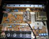
Below are some initial pictures of the condition as I received it from Goodwill. The pictures don't show how dirty it is. It's very sticky inside and out and I'm sure it has been around lots of smoke.

picture.php
 

Attachments

  • pic5.jpg
    pic5.jpg
    108.4 KB · Views: 337
  • pic6.jpg
    pic6.jpg
    133.7 KB · Views: 337
  • pic4.jpg
    pic4.jpg
    60.8 KB · Views: 271
Last edited:
Register to hide this ad
Very Nice Find....You will NEED to DeoxIT ALL the switches. This is the Achilles Heel of these HK's.

I try to use the same Brand cap to keep things even (so I think)..:D

Cap Brand Used:
Big Cans: Nichicon KW or you can use Nichicon KG
Standard Caps: ELNA SILMIC II
Replace Tantalum Cap at C228, C221,C275 & C272 with Film Panasonic ECQ
C307 & C305 with film Panasonic ECQ
C101 & C102 I use Nichicon ES(this is what I had)...You can use ELNA SILMIC II

Cap list will follow..I am going thru the Mouser List.

This is what I have done:

picture.php
picture.php

picture.php

picture.php
 
Looks like you did a good job on the recap. :thmbsp:

How did it sound afterwards?

Look forward to the cap list.

Thanks,
Tony
 
The restoration begins!

The parts I ordered arrived so I can finally start the restoration.

The first thing I did was repair the signal meter. The needle was stuck in the center and would not move regardless if power was applied or not. Took it apart, cleaned & lubed it and made some adjustments to the pivot tension. It seems to work now. Yay!

Next, I replaced the bad bulbs. This unit has the fuse bulb type and I noticed some of them had loose end caps even though they still showed continuity so I replaced them also just for reliability purposes.

Before starting the recap I decided to clean all the pots and switches to get it out of the way. So they all got to know my friend, Mr. Deoxit. Since I had the front end apart to fix the signal meter and bulbs, I recapped the board which has all the pots and switches soldered.

For the remaining 4 circuit boards I will try and take some pictures of before and after restoration. Along with the recap I also attempt clean the boards and make everything look half way decent.
Am I wasting my time posting this? Is anyone interested in reading or seeing pictures of the restoration?

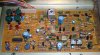
Here are the before and after pictures of the power supply board recap. Yeah, I went a little heavy with the glue. :no: Oh well, live and learn. :)

Before:
picture.php


After:
picture.php
 

Attachments

  • PS_before.jpg
    PS_before.jpg
    100.8 KB · Views: 218
  • PS_after.jpg
    PS_after.jpg
    103.1 KB · Views: 215
Last edited:
No reason to use glue in the first place. Only reason it was used in the original build, was to speed up the production process and support components for automated wave soldering and shipping stabilization.
 
Last edited:
No reason to use glue in the first place. Only reason it was used in the original build, was to speed up the production process and support components for automated wave soldering and shipping stabilization.
Perhaps but I like the extra support especially for the larger one's.
 
I have now completed the tuner board. Along with the lytics, I also replaced the four tantalum caps and deoxed the two trimmer pots.

Okay, here are the pics but it's nothing earth shattering: :)

Before:
picture.php


After:
picture.php
 

Attachments

  • TB_before.jpg
    TB_before.jpg
    103.4 KB · Views: 190
  • TB_after.jpg
    TB_after.jpg
    106.9 KB · Views: 196
I think you're the first to glue down the caps. ;) This is a fun thread to follow.
Glad you are enjoying it. I'm definitely enjoying doing the restoration and showing my progress.

Below is a pic of my tiny little work area. I did have a nice spacious setup down in the basement but in order to make the wife happy, I had to allow my brother-in-law to move into our basement. :no: So now I have this little work space upstairs with barely enough room to do actual work. At least it's in front of the TV. ** SIGH ** Happy wife, happy life right?

picture.php
 

Attachments

  • WA1.jpg
    WA1.jpg
    94.8 KB · Views: 171
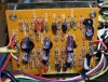
Up next we have the EQ/phono board. The only issue I ran into on this board was a cap value. Printed on the circuit board, the values for the two input caps is 10uF @ 35V. However, there were two 22uF @ 10V caps installed. I referred back to the schematic and it had the two caps listed as 22uF so that is what I installed.

Before:
picture.php


After:
picture.php
 

Attachments

  • EQ_before.jpg
    EQ_before.jpg
    102.4 KB · Views: 160
  • EQ_after.jpg
    EQ_after.jpg
    122.1 KB · Views: 169
Main Amp Board

The last board to be re-capped is the main amp board. Along with replacing the caps I also deoxed the two trim pots and decided to change the thermal paste as some of it was getting hard. It was getting close to the end of it's life span.

As an experiment, I decided to use some Artic Silver compound, since I had some laying around not being used, instead of the traditional white heatsink paste. The Artic Silver is gray looking.

The first thing I did was to remove the heatsink from the circuit board and take it completely out of the unit. For reference, the easiest way to do this is after desoldering the main output transistors from the circuit board is to remove the two screws holding the main amp circuit board to the chassis. Then remove the 5 screws holding the rear panel to the chassis. This allows you sufficient room to remove & reinstall the heatsink.

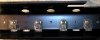
Here are some pics of the heatsink with the replacement of the thermal paste:
Before:
picture.php


After:
picture.php


Here are some before and after pix of the whole main amp assembly:
Before:
picture.php


After:
picture.php


So all the re-capping has been completed. I guess the next step in the restoration is make sure all my voltages are present, adjust the bias and offset voltages and make sure the unit is working properly after the recap.

Then I will start the restoration of the outside of the receiver. Basically it is just a good cleaning and polish of the faceplate and knobs. I also have to fix a little dent on the edge of the faceplate.
 

Attachments

  • HS_before.jpg
    HS_before.jpg
    52.6 KB · Views: 162
  • HS_after.jpg
    HS_after.jpg
    42.2 KB · Views: 157
  • AMP_before.jpg
    AMP_before.jpg
    86.1 KB · Views: 167
  • AMP_after.jpg
    AMP_after.jpg
    90.5 KB · Views: 168
I decided to use some Artic Silver compound, since I had some laying around not being used, instead of the traditional white heatsink paste. The Artic Silver is gray looking.

Beware !! Some of that artic silver stuff is electrically conductive and will short out your power rails... Read the AS specs before applying power.
 
Last edited:
+1 with AVIONIC! Get rid of the ARTIC SILVER! Only use white silicon based Stuff. i've seen transistors blow apart from ARTIC Silver! Clean it all off, (wash the heatsink if you have to, clean the backs of the transistors with alcohol and a clean wipe, also the mica's), the replace with the white compound BEFORE you plug it in!

Larry
Nice Thread....Nice time pass on the Glue. I will agree...ARTIC Silver should NOT be used. This is a conductive compound.
 
What ever you used for compound, it was way too much!!! A little goes along way.


Barney
 
I have not plugged it in yet but before I used the Artic Silver I checked out the datasheet and it specifically states that it is NOT electrically conductive, only thermally conductive otherwise I would not have used it. I am using the original Artic Silver 5 compound and not some cheap knockoff or copycat brand. So I am inclined to give it a shot but have not made up my mind yet given all the warnings from you AK'ers.

I will not get back to it until later this evening so I'll think about it for a few hours.

Regardless & no matter what happens, thanks for the heads up. :thmbsp:
 
Last edited:
Not Electrically Conductive:
Arctic Silver 5 was formulated to conduct heat, not electricity.
(While much safer than electrically conductive silver and copper greases, Arctic Silver 5 should be kept away from electrical traces, pins, and leads. While it is not electrically conductive, the compound is very slightly capacitive and could potentially cause problems if it bridges two close-proximity electrical paths.)

the compound is very slightly capacitive and could potentially cause problems if it bridges two close-proximity electrical paths.)

Something to keep in mind.
 
Nice thread, I just picked up a 330c at my local goodwill for 10 bucks. Works like a dream, although my power meter is stuck in the 0 position. How did you go about freeing yours up?
 
Back
Top Bottom