House de Kris
Loud-n-Deep
This is one of those topics that comes bouncing back about once a week here at AudioKarma, the notion of low-power amps destroying speakers. When I first heard of this theory decades ago, yeah, it made sense. Clip a signal, create sharp edges in time, thus create high frequency energy. Makes sense to me. I grasped that idea and ran with it for years.
More recently learned people have been implying this isn't really the issue. Their views make sense as well. In a recent thread on this very topic here at AK ("Amp power Vs. Speaker"), pustelniakr made this comment:
When someone says data is far from necessary, I take that as a challenge. Heck, I'm much more than interested myself. Thus, I decided to whip up a little program to simulate the effects of clipping and measure the results. First of all, I must say, I'm no programmer, and it has been years since I've written a VEE program, but VEE is a simple language created pretty much exactly for these types of "what if" scenarios. After many hours of sitting in front of a terminal feeling stupid for forgetting so much of the basics of VEE, I finally got something useful. I've decided to share the results here. I'm not claiming to be the ultimate guru on this topic, so if I've done something wrong in my logic, or made bad assumptions, please set me straight.
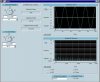
I was hoping to share the program with anyone interested, but I haven't gotten it to work in the run-time environment, only the development environment. Perhaps in another week or so... At any rate, I took screen shots of the clipping simulator with several different degrees of clipping going on, so we could see how much energy is in the higher regions. I'll go over the features of the screenshots in detail for the first picture, barely clipping, and then show the other pictures which have higher degrees of clipping, and greater high frequency energy.

The screenshot has two knobs and two displays. The knobs are used to set the degree of clipping and the displays show the effects of clipping. The upper knob, "Desired Amplitude," sets the amplitude of the desired wave, if the signal weren't clipped. The units of this knob are volts, so think of this as the maximum unclipped amplitude that is desired. To the right of this is a display that indicated the maximum peak power this would develop into an 8ohm load. In this example, the knob is set to 40, which implies the signal will travel between +/-40V unclipped. The display indicates that this is 200W at the peak voltage. The lower knob sets the actual clipping voltage that a particular amp may exhibit. In this example, I've got it set to 39.75V, or in other words, 250mV is being clipped off of the top and bottom of the waveform. The calculated power at clip is 197.5W. The "Clipping Amount (dB)" display shows how much of the signal has been clipped, and in this example is 0.05446dB - not much at all. The Waveform display shows both waves, with the unclipped wave in yellow and the clipped wave in blue. You can just barely see the yellow tops above the clipped blue ones. The Spectrum display again has both waves displayed, but we're really only interested in the blue clipped one. For this example (and the others as well), I put the markers on the 200Hz fundamental, and the third harmonic at 600Hz. The Spectrum display tells us that the third harmonic is at 22.49mV. I added a handy power calculator below the Spectrum display to translate this to power into 8ohms. In this case, it is a whopping 63uW. If you can't think in microwatts, it is 0.000063W.
By the way, the wasted space near the Clip Threshold knob is for other versions of this software with greater capabilities. One version allows me to set Vcc and Vee Clip Threshold independantly, to simulate asymmetrical clipping, and another version allows me to control the voltage of the clip area to simulate latch-up or power supply droop. Many more knobs, but not so useful for this thought exercise. One other thing, the ugliness of the traces is due to the resizing of the pictures in order for AK to accept them. I could have (should have) remade my panel to the appropriate size and regrabbed the screenshots, but I'm lazy.
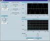
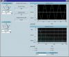
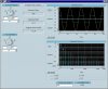
The other three examples I did have greater amounts of clipping to really get a feel for what kind of energy is on tap in a clipping situation. I have the Clip Threshold set to 30V, 20V, and 10V. This gives rise to Clipping Amounts of 2.5dB, 6dB, and 12dB, respectively.

Let's jump to the worse case one, 10V/12dB, to see what sort of energy there is. In this case, again, we have the levels set for a clean signal if our amp could supply 200W into 8ohms. But, the amp we're using has power supply rails so low that it can only pass a 12.5W signal without clipping. Right, we've got it so loud that we should have a 200W amp, but we're using a 12.5W amp. 12dB of signal is clipped right off. The third harmonic is 3.84V, or 1.843W. Frankly, IMO, if someone is clipping this severly, they deserve to blow a tweeter or two.
All in all, less power is generated on a clip than what I was assuming going into this experiment. Several interesting things become evident when playing around with this software, but nothing earth shattering. Going further, I would like to add a summer to sum the total power of the harmonics. Or, better yet, be able to set what the crossover frequency is to the tweeter to sum just those frequencies. And, have a variable frequency clipped signal, to boot. This would give a much better idea of the total heating power delivered to a tweeter voice coil. Alas, it was hard enough to bang out this little bit of code in a week for me.
I hope this was useful to other AKers. I know it actually has been an eye opener to me.
More recently learned people have been implying this isn't really the issue. Their views make sense as well. In a recent thread on this very topic here at AK ("Amp power Vs. Speaker"), pustelniakr made this comment:
Clipping a signal (limiting positive and/or negative excursions) limits the power at the clipped frequencies. As a signal approaches a square wave, what you get is a fundamental and all of the odd harmonics. Indeed, some additional energy IS being fed to the tweeters. Is it enough, by itself, to fry the tweeters and midranges? Lets see some hard math. I'm interested. But it is far from necessary.
When someone says data is far from necessary, I take that as a challenge. Heck, I'm much more than interested myself. Thus, I decided to whip up a little program to simulate the effects of clipping and measure the results. First of all, I must say, I'm no programmer, and it has been years since I've written a VEE program, but VEE is a simple language created pretty much exactly for these types of "what if" scenarios. After many hours of sitting in front of a terminal feeling stupid for forgetting so much of the basics of VEE, I finally got something useful. I've decided to share the results here. I'm not claiming to be the ultimate guru on this topic, so if I've done something wrong in my logic, or made bad assumptions, please set me straight.
I was hoping to share the program with anyone interested, but I haven't gotten it to work in the run-time environment, only the development environment. Perhaps in another week or so... At any rate, I took screen shots of the clipping simulator with several different degrees of clipping going on, so we could see how much energy is in the higher regions. I'll go over the features of the screenshots in detail for the first picture, barely clipping, and then show the other pictures which have higher degrees of clipping, and greater high frequency energy.
The screenshot has two knobs and two displays. The knobs are used to set the degree of clipping and the displays show the effects of clipping. The upper knob, "Desired Amplitude," sets the amplitude of the desired wave, if the signal weren't clipped. The units of this knob are volts, so think of this as the maximum unclipped amplitude that is desired. To the right of this is a display that indicated the maximum peak power this would develop into an 8ohm load. In this example, the knob is set to 40, which implies the signal will travel between +/-40V unclipped. The display indicates that this is 200W at the peak voltage. The lower knob sets the actual clipping voltage that a particular amp may exhibit. In this example, I've got it set to 39.75V, or in other words, 250mV is being clipped off of the top and bottom of the waveform. The calculated power at clip is 197.5W. The "Clipping Amount (dB)" display shows how much of the signal has been clipped, and in this example is 0.05446dB - not much at all. The Waveform display shows both waves, with the unclipped wave in yellow and the clipped wave in blue. You can just barely see the yellow tops above the clipped blue ones. The Spectrum display again has both waves displayed, but we're really only interested in the blue clipped one. For this example (and the others as well), I put the markers on the 200Hz fundamental, and the third harmonic at 600Hz. The Spectrum display tells us that the third harmonic is at 22.49mV. I added a handy power calculator below the Spectrum display to translate this to power into 8ohms. In this case, it is a whopping 63uW. If you can't think in microwatts, it is 0.000063W.
By the way, the wasted space near the Clip Threshold knob is for other versions of this software with greater capabilities. One version allows me to set Vcc and Vee Clip Threshold independantly, to simulate asymmetrical clipping, and another version allows me to control the voltage of the clip area to simulate latch-up or power supply droop. Many more knobs, but not so useful for this thought exercise. One other thing, the ugliness of the traces is due to the resizing of the pictures in order for AK to accept them. I could have (should have) remade my panel to the appropriate size and regrabbed the screenshots, but I'm lazy.
The other three examples I did have greater amounts of clipping to really get a feel for what kind of energy is on tap in a clipping situation. I have the Clip Threshold set to 30V, 20V, and 10V. This gives rise to Clipping Amounts of 2.5dB, 6dB, and 12dB, respectively.
Let's jump to the worse case one, 10V/12dB, to see what sort of energy there is. In this case, again, we have the levels set for a clean signal if our amp could supply 200W into 8ohms. But, the amp we're using has power supply rails so low that it can only pass a 12.5W signal without clipping. Right, we've got it so loud that we should have a 200W amp, but we're using a 12.5W amp. 12dB of signal is clipped right off. The third harmonic is 3.84V, or 1.843W. Frankly, IMO, if someone is clipping this severly, they deserve to blow a tweeter or two.
All in all, less power is generated on a clip than what I was assuming going into this experiment. Several interesting things become evident when playing around with this software, but nothing earth shattering. Going further, I would like to add a summer to sum the total power of the harmonics. Or, better yet, be able to set what the crossover frequency is to the tweeter to sum just those frequencies. And, have a variable frequency clipped signal, to boot. This would give a much better idea of the total heating power delivered to a tweeter voice coil. Alas, it was hard enough to bang out this little bit of code in a week for me.
I hope this was useful to other AKers. I know it actually has been an eye opener to me.