• The move to the new server is done. There are some software and database maintenance updates in process. This has us passing the hat around to help out. We appreciate any donations. Seriously, even a dollar helps. The payment page may be found here - https://www.audiokarma.org/support.html

Double the life of your caps?

ConradH

Lunatic Member
Cap life is highly dependent on temperature. If filter cans are mounted right next to the rectifier tube, they won't last long. Can't do much about that other than move them or install a heat shield.

There's a more subtle issue seen in many tube amps, but even some solid state ones. Very often hot voltage dropping resistors are mounted right to the capacitor lugs. The heat is conducted down the lugs and into the body of the cap. It may be a convoluted path through the internal connections, but if you can reduce the temperature in there by 10 degrees, cap life can double.

Ever notice how old FP cans with dropping resistors are always shot? Ever notice how cans mounted away tubes and without dropping resistors seem to last forever? They should all be replaced by now, but why not give the expensive new parts a break? They don't cost $1.75 like they used to!

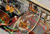
The solution is simple. Just move the dropping resistors to a nearby terminal strip. These photos clearly show bad wire dress, old line caps and other things that need to be attended to, but if you can ignore all that, they also show how to move the resistors off the cap. (don't worry about bleeder resistors unless they run quite warm)
 

Attachments

  • hotcap.jpg
    hotcap.jpg
    70.9 KB · Views: 155
  • coldcap.jpg
    coldcap.jpg
    80.9 KB · Views: 155
Last edited:
Register to hide this ad
My thoughts exactly,,, I've been doing it on the last few projects...

Regards,
John
 
Last edited:
personally I don't care for the cluster of resistors on the bottom of the cap anyway. I find it to be messy. Unfortunately sometimes you have no choice in the matter in compact amplifiers.
 
Yeah, space, the final frontier, but I never seem to have enough of it!

Another one to think about is what you commonly find in console amps like Stromberg Carlson. The cathodes of the output tubes often go through a single or double RC to ground.

The original parts might be mounted in parallel on a terminal strip, and the big old tubular cap might be (yes, I measured) 0.682D by 1.79L, for a surface area of 4.56 in^2. It's dead by now, so you replace it with a modern cap of 0.322D by 0.48L for a surface area of 0.648 in^2. That's a factor of seven difference in surface area! Though the new cap might have much better specs in every way, it just can't stay as cool as the old one when you inject heat from the parallel resistor.

I haven't done this but there are two reasonable solutions. First, replace the terminal strip with one having a couple extra lugs. Now offset the power resistor and cap by one position, and tie them together with short loops of not-too-large wire. Another way might be to mount another identical terminal strip next to the first, using the same chassis holes, so they're about 3/8" apart. Mount the resistor on one, the cap on the other, and again use loops to connect. If you want to guild the lily, use constantan or manganin loops because the thermal conductivity is way lower than copper. Tie the circuit to the cap side so the extra fractional ohm resistance doesn't end up as undesired esr in the cap.

I've seen the same problem on circuit boards, where some power resistor is allowed to conduct heat through a big trace, right into a cap. Gets you through the warranty period, but not through 10-20 years of ownership.
 
Conrad,
This is one of those obvious things that really isn't obvious at all.
Thank you.
Your observation is brilliant and I will be doing things differently from now on because of this post.
 
In cases where heat looks to be an issue, I tend to go up greatly in voltage value, on the new cap, as much as possible. Not only does that get a cap that's usually closer to the physical size of the old cap- but as you will be using the cap at only a fraction of its maximum voltage, it will last a LOT longer, even in a hot environment.

Regards,
Gordon.
 
In cases where heat looks to be an issue, I tend to go up greatly in voltage value, on the new cap, as much as possible. Not only does that get a cap that's usually closer to the physical size of the old cap- but as you will be using the cap at only a fraction of its maximum voltage, it will last a LOT longer, even in a hot environment.

Regards,
Gordon.

I've done that also, as it seemed like a good idea,, but I've also read that if you use a lot higher V cap, they will never form, and won't work properly,,,
However, I haven't noticed any problems in amps I've worked on, and now, with your experience, I have to believe its a good thing to do!
 
Last edited:
Over the years all aluminum electrolytic caps tend to fall back to a level of forming consistent with whatever operating voltage they run at. Increase the voltage and the DC leakage will greatly increase until they either reform to the new level, or fail if the current is too high. In tube equipment it may not be possible to increase the voltage by much, but in general I try for a significant safety margin. Operating at 60% or so of rating will definitely improve life. Somewhere I've got a formula for it. I've never seen a problem with higher voltage caps in lower voltage circuits. It was either something from the past that isn't a big deal today, or maybe an old wives tale. Still, if you can keep 'em cool it's always beneficial.
 
Last edited:
Doing some updating on an old Zenith 7 tube radio, a big old black beauty cap across the ac line laying right next to the selenium rectifier. After ten minutes or so the rectifier hits about 150 degrees. Not good for that old cap I suspect. Burn down the house?
 
Tight quarters in old gear is not one of it's better features. I have a 6 tube octal based AA6 type radio made by Westinghouse. Its packed like sardines, and an absolute SOB to work on. Parts are all jammed in there, and there isnt much you can do about it. I'm surprised that when I got it, it was all original and actually functioned with original parts once I replaced the single dead tube. There are a number of parts packed against heat generators. Its also vertically oriented with the multicap towards the top of the stack.
 
Heat sinks and caps. in SS gear.

What I see in much SS gear is the capacitors associated with regulator IC's is they place the capacitors INSIDE the hollow part of the heat sinks, right next to the regulators, when I see that, that is the first place I check if there are PS problems, most of the time they are dried out and bad. :no:

BTW, here is the most common thing I see with electrolytic caps. given the same location to a source of heat, a SMALL sized cap. will tend to "go bad" first before the larger one (a small "container" will lose moisture faster then a larger one). :scratch2:

Mark T. :music:
 
Excellent posts Conrad, another one to add to my reference library of tube gospel. Simple, heat kills electronics, so why expose components to the heat of others.
 
Great thread. I hope to start reading some books and get a little more confortable with electricity. I see a Eico HF 20 in my future.
 
Other factors come into play as well. One of the issues of heat- You see it sometimes in consumer gear, and many times you do not- Power resistors elevated above the PC boards, sometimes wrapped in a heat resistant sleeve, and sometimes not. While copper is an effective conductor of heat, that small diameter is only going to be able to transfer a slight amount of heat when compared to what disipates off the body of the resistor. if the resistor is kept further away from the phenolic boards, active devices and electrolytic capacitors, the longer the components last.

Moving the resistor off of multi section can caps is good practice, and easy to accomplish when rebuilding or building custom low production amps, but when you are talking production of say 10,000 units, you are usually looking to trim costs where you can. Which is why the resistors were soldered to the cap and not on a terminal strip as Conrad is showing. It was not done because of cost.

With a 90 day warranty on many of those vintage items when they were new, it did not matter if the life of a 2000 hour capacitor was cut to 1000 hours due to heat of a resistor. In most cases, 1000 hours of use usually was about how long something was in service before it was replaced with something newer.

If you managed to get less than a 10% rate of failure in the first 100 hours of use (from defective tubes, bad bulbs, etc), chances were good the rate of failure would diminish to nearly zero for the period of time between 100 to 2000 hours to a very slight percentage of units at 2000 hours only to increase again slowly (initially) after 2000 hours of use, and if you achieved that product reliability curve, you would see that as a profitable product.

When I can, I leave the resistors a bit further from the terminal strips or off the PC board as much as I can due to those resistor leads being limited in the amount of heat they can actually transfer.
 
Back
Top Bottom