


WBloodworth
New Member
I'm doing an AM/FM alignment on a 2215B and I can find no information in the service manual or anywhere on the internet to indicate how the trimmers are oriented on the variable capacitor.
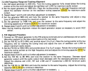
As you can see here, the service manual refers to these 5 points for adjustment:
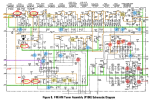
And we can see on the schematic that I have circled them in red:
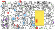
I have "guessed" on this screenshot of the board layout as to the orientation of these adjustment points (highlighted in yellow):
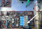
My guesswork is based on this screenshot of the actual board in the same orientation as the board layout above. The AM instructions refer to CA-2 and we can see that the orange wire (from the AM stick antenna) is connected to the second terminal from the bottom. Therefore, I assume the adjustment points are as shown on the image.
Do I have these listed in their correct orientation?
Thank you,
- Wil
As you can see here, the service manual refers to these 5 points for adjustment:
And we can see on the schematic that I have circled them in red:
I have "guessed" on this screenshot of the board layout as to the orientation of these adjustment points (highlighted in yellow):
My guesswork is based on this screenshot of the actual board in the same orientation as the board layout above. The AM instructions refer to CA-2 and we can see that the orange wire (from the AM stick antenna) is connected to the second terminal from the bottom. Therefore, I assume the adjustment points are as shown on the image.
Do I have these listed in their correct orientation?
Thank you,
- Wil

