• The move to the new server is done. There are some software and database maintenance updates in process. This has us passing the hat around to help out. We appreciate any donations. Seriously, even a dollar helps. The payment page may be found here - https://www.audiokarma.org/support.html

2220 (non b) Low Channel Output - Help Requested

Jamie Starr

Active Member
Hey All: I recently did a minor restoration on a 2220. After cleaning it up, it sounded fine and I do not recall seeing anything unusual on the O-scope. I changed out the caps on the power board (P800), tone board (P500), amplifier board (P700), all 3 big caps (C004.C005,C006), all 4 pots on P700, and the output transistors.

I checked my work after each stage and did not see any shorts or distortion. I did not have any trouble setting "audio adjustments" per the manual.

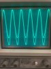
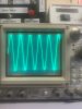
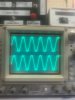
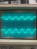
During final testing, I noticed that the right channel on the scope was not tracking in-line with the left. No distortion on scope but it had less volume or power on the scope. I figured that it was close and could not hear much of a difference on my test speakers.

Once I connected 2220 to more substantial speakers, the difference in the channels was quit noticeable. Here are pics of what I am getting on the scope.

I have tapped around the boards and used freeze spray, but have been able to locate any problem. Any suggestions on how to troubleshoot this? Am I looking for a cap installed backwards? Loose wire? Transistor? Again, I don't think this was there before I worked on it, so I will take the blame. Thanks
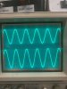
2220 a.jpg 2220 b.jpg 2220 c.jpg 2220 e.jpg
 
Register to hide this ad
I would look at the left and right Tape record out's, and the inputs to the driver board, with a scope. You should be able to help localize the issue that way. Be aware that the weak channel may not be the one with the defect. I have seen issues where the strong channel was the defective one, usually caused by insufficient negative feedback in some amplifier stage.
 
I would look at the left and right Tape record out's, and the inputs to the driver board, with a scope. You should be able to help localize the issue that way. Be aware that the weak channel may not be the one with the defect. I have seen issues where the strong channel was the defective one, usually caused by insufficient negative feedback in some amplifier stage.
Thank you. I will look there too. I am tending to think is has to be something on the boards I worked on, as I do not recall this much variance between the channels before I worked on it. SMH :no:
 
:lurk:I've got a 2220 with the same problem. Was like that when I bought it. Sounds good, just an output imbalance between channels.
Interesting. I should’ve paid more attention before I change capacitors to see if the problem was already there. I didn’t have much time tonight to try to isolate the problem. However, I did hook the scope up directly to the headphone output. The problem was not there, until I pressed the main speaker button and had a load on it. Then the drop on right channel showed up, which confuses me, because I thought the headphone output was coming from the preamp board and bypassing the amplifier??? When I disconnect the speaker, the levels tracked almost perfect??? Even with the main speaker button pressed in and no load. But when speaker hooked up, the drop in level is there. I’m gonna poke around some more when I get some time. To me the imbalance between the two channels is a little too much to be how it should work. We will see or I will keep scratching my head.
 
The headphone jack is fed from the main amplifier output (the same as the speakers), there is just a 100 ohm resistor in series with each channel to prevent the headphone jack from presenting a dead short to the amplifier. The output is capacitor coupled. A weak output capacitor could cause the issue. An open choke (L003 or L004) in the output would cause a slight drop in output, as it would place a 2.2 ohm resistor in series with the speaker output. These issues would not effect the level in headphones very much due to their higher impedance.
 
Last edited:
Interesting. I should’ve paid more attention before I change capacitors to see if the problem was already there. I didn’t have much time tonight to try to isolate the problem. However, I did hook the scope up directly to the headphone output. The problem was not there, until I pressed the main speaker button and had a load on it. Then the drop on right channel showed up, which confuses me, because I thought the headphone output was coming from the preamp board and bypassing the amplifier??? When I disconnect the speaker, the levels tracked almost perfect??? Even with the main speaker button pressed in and no load. But when speaker hooked up, the drop in level is there. I’m gonna poke around some more when I get some time. To me the imbalance between the two channels is a little too much to be how it should work. We will see or I will keep scratching my head.

So putting an 8ohm (?) load from the speakers on the amp causes a drop in voltage/power. What is the load from the phones? If the phones are plugged in, does that cause a drop? <<<what goes through a rookies cabeza when thinking about this.
 
The headphone jack is fed from the main amplifier output (the same as the speakers), there is just a 100 ohm resistor in series with each channel to prevent the headphone jack from presenting a dead short to the amplifier. The output is capacitor coupled. A weak output capacitor could cause the issue. An open choke (L003 or L004) in the output would cause a slight drop in output, as it would place a 2.2 ohm resistor in series with the speaker output. These issues would not effect the level in headphones very much due to their higher impedance.
Thank you for that explanation. It makes sense as to what I was seeing on the scope. I will check out that resistor and choke. However, I do not have any experience with "chokes," and if I recall, every time I have tested them on a multimeter, they always show open. So I will do some research.

I can tell you this, after reading your post I put a multimeter on C004 and C005 on their negative terminals to the terminal where the resistor and choke L003 and L004 attach. C005 had a reading of approx. 3.2 ohms and C004 (which I think is for the right channel) had a reading of .003 ohms. Hmmmmmm
 
Last edited:
So putting an 8ohm (?) load from the speakers on the amp causes a drop in voltage/power. What is the load from the phones? If the phones are plugged in, does that cause a drop? <<<what goes through a rookies cabeza when thinking about this.
No. No drop when go from headphone jack directly to oscilloscope. Drop is present when I push in the main speaker button AND there is a speaker and/or 8 ohm load hooked up. If I press it in with no load, then no drop in voltage power on right side. I have a rookie cabeza too.
 
I'm with Pete, wiggle the coil and see if one end moves around as in the solder joint is cracked or just not soldered correctly.
Thanks for the suggestion. Will do. Could one of you guys explain the purpose of the choke? It appears to be a different type of resistor? Am I understanding that correctly? I plan to resolder to the negative leads on C004 and C005 to the 2.2 ohm resistor and the choke. Is there anything I need to know about the choke before doing this? It does not look like a very precise passive component. I may have to snip off an 1/8 inch or so off one end, is that going to be a problem? Finally, how do I remove the copper coating to get to the conductive matter? Thanks
 
The choke and resistor form a damped isolation network to decouple the high frequency output of the amp from the speaker terminals. Without the choke in series with the output, a rather large capacitive load on the speaker terminals could load down high frequencies at the output of the amplifier, causing insufficient high frequency negative feedback, which could cause the amplifier to go into oscillation (at a high ultrasonic or even RF frequency). The actual values of the components are not very critical. I would just be sure that the choke is well connected, as the signal goin to the speaker is through the choke. The resistor is there to damp the circuit, and lower the Q of the choke, so some resonance is not setup.
 
Last edited:
The choke and resistor form a damped isolation network to decouple the high frequency output of the amp from the speaker terminals. Without the choke in series with the output, a rather large capacitive load on the speaker terminals could load down high frequencies at the output of the amplifier, causing insufficient high frequency negative feedback, which could cause the amplifier to go into oscillation (at a high ultrasonic or even RF frequency). The actual values of the components are not very critical I would just be sure that the choke is well connected, as the signal goin to the speaker is through the choke. The resistor is there to damp the circuit, and lower the Q of the choke, so some resonance is not setup.
Wow. Thank you for that explanation. I did not realize how important the choke and small resistor were to the amp. Sounds like if that is not connected soundly, the amp could go haywire. Can you advise how to get to the conductive material in the coil? Sand off the outer coating? Thanks
 
Just scrape the surface where it is connected, so the solder will make a good connection.
 
Once again you guys are correct. It appears that I did did not have a good connection on one of the chokes and the coupling capacitor. I re-soldered both chokes and resistors and made sure the connections were sound.
Now both channels are tracking evenly and sounds much better.
Can’t thank you enough for your guidance.
 

Attachments

  • A642B44D-9FF2-4CD1-B23E-51F416667B9D.jpeg
    A642B44D-9FF2-4CD1-B23E-51F416667B9D.jpeg
    70.9 KB · Views: 11
  • 7F2651B9-CD91-42BF-84E7-AEAA7FE2D7F6.jpeg
    7F2651B9-CD91-42BF-84E7-AEAA7FE2D7F6.jpeg
    72.8 KB · Views: 10
Back
Top Bottom