• The move to the new server is done. There are some software and database maintenance updates in process. This has us passing the hat around to help out. We appreciate any donations. Seriously, even a dollar helps. The payment page may be found here - https://www.audiokarma.org/support.html

2220 Power Amp Burnt Resistor (R753) - Cause? SOLVED

So I decided to go back to square one and check out the power supply - I should have started there, anyway. I don't like that H802 is universally ~25% low...

All the electrolytics are new on this board, as is H802 (replaced with KSC2383YTA), everything oriented properly. H804 / H805 are original, as are C801 / C802. Hmm.

P800 board: actual DC voltage (reference DC voltage)
  • H802 E 27.5 (35) | C 30 (42) | B 28 (35.6)
  • J810 9.9 (14.6)
  • J808 27.5 (35)
  • J809 11.3 (12)
I wonder if this points to the transformer? Knock on wood.
 
Last edited:
Possibilities include but not limited too:
C803 bad.
H804 or H805 bad
Low line voltage to transformer (bad power switch?)
Bad transformer (least likely)
Tom
 
Changed H804, H805, and H808 out for UF4005s that I had ordered from Mouser but not installed. All measured voltages are the same and the S1B-01-02s that came out all tested good.

I then measured the AC voltages coming in from the transformer. H801 and H803 measured 29VAC. This is 8VAC less than the voltage reported in another thread, and another thread.

I suppose I need now to check the transformer's feed voltage.
 
Last edited:
My dim bulb tester must be limiting the incoming voltage. I'm only getting 96VAC in the power cord from the DBT. So that, I suppose, answers that question.

I guess it's safe to call the Power Supply healthy? And will move back to the amplifier board & coupling caps.
 
Went back to the Power Amplifier, P700 today. Measured all of the pins at the bottom.

P700 board: actual measured voltage (reference voltage). Most seem ballpark considering that the DBT is dropping some of the power supply voltage. Concerns in bold.

J710: 36.4 VDC (+ side of C006)
J714: 20.2 VDC (21.9)
J712: 18.2 VDC (22.5)
J720: 0 VDC, 9.6 VAC (- side of C005)
J716: 19.2 VDC, 7.0 VAC (23 VDC)
J718: 19.1 VDC (21.8)
J722: 0.5 VDC (0.51)
J724: 0 (grnd, - side of C006)
J723: 0 (grnd)
J721: 0.5 VDC (0.51)
J717: 18.7 VDC (21.8)
J715: 18.8 VDC, 7.4 VAC (23 VDC)
J719: 0 VDC, 1.3 VAC (- side of C004)
J711: 19.5 VDC (22.5)
J713: 18.9 VDC (21.9)
J709: 36.4 VDC (C of H001, also + side of C006, service manual is missing the link!)

I then checked for any A/C voltage across the pins of the main cap (C006) and the two coupling caps (C004 and C005). Initially I got a steady 2 VAC across one of the coupling caps, but soon it joined the others in oscillating between 0 and Overload on my digital meter.

What have I learned? Well, I'm not sure, but the presence of A/C voltage at J720 and J719 seems to be the loud hum that comes from the speakers / headphones when connected. So my current hypothesis is that this A/C voltage is going back through C725->R753 and C726->R754 which is causing the resistors to heat up.

But assuming this is the problem, how do I solve it? I have no idea, because it isn't obvious (to me) where this A/C voltage could be coming from. The + side of each coupling cap (C004, C005) is J715 and J716, both of which appear to be reading (approximately) the appropriate DC voltage ...

Thanks in advance to anyone who is thinking about this with me.

Edit: Just measured the + side of the two coupling caps (C004, C005) and found +7.0 VAC on one, +7.4 VAC on the other (to ground). These are J715 and J716.

So, it seems I have + AC voltage on both sides of each coupling cap. How could that be?
 
Last edited:
I have a theory. I could be way off here. But I spent the night reading up on how coupling capacitors work. Thanks to everyone on AK for all the fantastic discussions about them. But I realized that one of the reasons they are there is to block the DC voltage (in this case the 23V at J715 and J716) and let the music, the AC voltage, pass through to the speakers. I had an epiphany that the AC voltage (the ~7 VAC) I'm seeing at J715 and J716 is the hum I'm hearing through the headphones!

After double and triple checking all the P700 power amplifier components again (and if this whole thing eventually comes back around to a bad component on this board, wouldn't that be ironic), I thought, what if the amplifier is just doing its job? What if it's getting a crazy input signal from the pre-amp section (in this case, the loudness / filter P600 board)?

So, I measured J701 and J702 and found ~0.25 VAC at each. I have no idea what it's supposed to be, but I had figured it should probably be 0 VAC, right? Since it's on AUX with nothing plugged in and volume at 0. I don't know the range the input signal is supposed to have - What if 0.25 VAC is really way too much? So I de-soldered J701 and J702 and powered it up. No more hum! No more bright light on the DBT! No more hot resistors!

What does this mean? I think it means that there's no short internal to the P700 power amplifier. If there was, it would continue to draw power (and make the DBT bright, and heat up those resistors) even in the absence of input signals from J701 and J702.

I think the next step will be to go upstream to P600 and see if the AC signal is originating here, or elsewhere upstream.
 
Keep up the good work! Do you have an external signal you could run into J701/702 to see if it plays correctly

Tony
 
FIXED! (Pending extended listening - at least not drawing current, not heating up, great FM on both channels in the garage.)

I traced the AC signal upstream ... found something definitely wrong. :idea:

I'll let the pictures speak for themselves (this is P650):

(@Aaron99 check it out ... same as yours!)

IJdnC2dl.jpg


KXD0csSl.jpg


pSfYdmsl.jpg


hGq0aAQl.jpg


:rockon::rockon::rockon::rockon::rockon:
 
Last edited:
Thanks - I want to see if I can do a post-op debrief and figure out why P700's R753 & R754 got fed so much current all because of P650's open J652 (one channel's signal output), J653 (the other channel's signal input), and J656 (ground). I would have thought that with both channels' signals, and the ground, disconnected through the bass/treble pots, instead of a loud hum, there should have been no sound at all? Hmm.
 
Such an interesting post!!!
so, all the problem was about some wires unsoldered/broken???
can you share thee diagram? i get one from hifi engine, but it shows the diagram of a 2220b, which has npn/pnp output transistors ...
regards
 
Man.. great job tracking that down.. reminds me of finding a wire in my 2245 that had been wrapped too close to a post and over the years, it wore through the jacketing to short out now and then. Drove me insane for a few weeks finding that damn wire.
 
Yes the problem was about some broken wires after all.

My thought - and I welcome any and all other thoughts - is that a broken J655 removed the ground connection through the tone controls, thereby reducing the number of grounds of P700 (the amplifier board) from 2 to 1 (the black wire to the chassis off J725). In so doing, the OPT power source current had to flow through R753/R754? Thus causing the overheating resistors as if there was a short, although in reality it wasn't a short but instead an open on the other side.

Would love to reach a conclusion as to what exactly was happening with P650's J652, J653, and J655 being open.

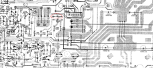
I've attached the schematic (@jFF_Bulbo it is also available on HFE) with red dots indicating the broken connectors and red lines indicating the broken ground downstream (I think).

I hope this link will take you to the marked up schematic in full size: https://imgur.com/MrVvVe9 (looks like you have to download it, and then you can zoom in)
 
I read all the pages of the post hoping to lean something. In the end it literally came down to broken wires. It frustrated me. Im not going to lie. Im glad you fixed it, but come on man. First thing you do when you crack the lid is clean and inspect throughly. Hope your friend appreciated the effort.
 
I'm certainly not proud of the process, but I'm happy with the result. I can say that most repairs I've done have been obvious in hindsight. I hope that you can repair whatever you're working on without too much extraneous effort!
 
Bro. I had the same problem on my pioneer sa-v1160 . 10ohm R259 Resistor keep burning 2-3 second when power on(without speaker connection) r259.PNG
 
Back
Top Bottom