So I purchased a working 2220b from the original owner. I set out to restore it -- changing lights, cleaning pots, changing out capacitors for most the boards (not AM/FM). I checked after working each board and it worked. But then I plugged it into my main speakers, which have these dumb Monoprice pin connectors for the spring clip terminals. Anyway, they got too close to one another, the metals touched, and created a short. At first I didn't know why, but I did figure out that it blew an output transistor. I replaced it and it worked when testing. But moving the receiver into its final home, the pin connectors touched again. Something else shorted and there's no sound coming from the unit. It still turns on and there's a faint click of the relay. But nothing going out to the speakers (I've since wrapped the pin connectors in lots of electrical tape). Any ideas where I should start? I don't see any visible shorts. I assume it's something on the power board. I have new power capacitors that I haven't put in (mostly because they're trickier to solder than the smaller ones). But if the unit is powering on, that wouldn't be the issue, right? Anyway, I appreciate any advice. And I apologize for any naïveté. I've only restored one other Marantz and some of the terminology and technique is foggy having not used these skills in a while.


You are using an out of date browser. It may not display this or other websites correctly.
You should upgrade or use an alternative browser.
You should upgrade or use an alternative browser.
Register to hide this ad

Welcome to AK! It sounds like you made a lot of progress before shorting the speaker outputs. Let's address that part first, then talk about the DBT that you need, then move into doing some fault isolation.
As you've found, the solid metal pin connectors suck. I have tried them by putting shrink wrap over them, but it was always worrisome. So for years I've used inexpensive angled pin connectors found on that auction site. They work perfectly with Monster XP speaker cable. And they work with all 4 types of spring clip speaker terminals used on the Japan produced models. And they don't short.
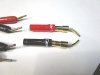
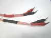
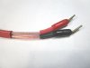
These pictures show a set that has been in daily use for years at my bench. The plating has worn off! But with the shrinkwrap reinforcement they have held up to constant connecting/disconnecting.
To work further on your 2220B, you need a Dim Bulb Tester. You can google it and find many ways to put one together. Typically they consist of an electrical outlet box with pair of plugs and an incandescent light bulb (100W works for all but the biggest models). The DBT routes the power through the light bulb to the outlet. When the stereo is plugged in and turned on, the lamp will glow brightly if there is a short somewhere, like in an output transistor. Or if you installed an output transistor in the wrong location. This is usually instead of the fuse blowing. If the lamp flashes briefly when the receiver is powered up, then goes dark, then that's good news. Then keep using the DBT, plugging into it each time you test the receiver. It will often save costly output transistors and fuses.
Next post: some things to look at
As you've found, the solid metal pin connectors suck. I have tried them by putting shrink wrap over them, but it was always worrisome. So for years I've used inexpensive angled pin connectors found on that auction site. They work perfectly with Monster XP speaker cable. And they work with all 4 types of spring clip speaker terminals used on the Japan produced models. And they don't short.
These pictures show a set that has been in daily use for years at my bench. The plating has worn off! But with the shrinkwrap reinforcement they have held up to constant connecting/disconnecting.
To work further on your 2220B, you need a Dim Bulb Tester. You can google it and find many ways to put one together. Typically they consist of an electrical outlet box with pair of plugs and an incandescent light bulb (100W works for all but the biggest models). The DBT routes the power through the light bulb to the outlet. When the stereo is plugged in and turned on, the lamp will glow brightly if there is a short somewhere, like in an output transistor. Or if you installed an output transistor in the wrong location. This is usually instead of the fuse blowing. If the lamp flashes briefly when the receiver is powered up, then goes dark, then that's good news. Then keep using the DBT, plugging into it each time you test the receiver. It will often save costly output transistors and fuses.
Next post: some things to look at
Please visually confirm that the relay is closing in its current state with all the output transistors installed. It is useful to know.
I think I'd start by confirming that power is getting to all the circuit boards. We know it is getting to the lamps, which confirms that it is plugged in and turned on. Heh. There are two other power circuits to check.
Note: all these tests are done with the bottom cover off and the unit powered up. Be careful.
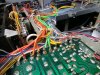
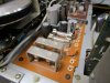
Each of the three power circuits has a pair of wires coming from the transformer to the P800 power supply board. They are conveniently all in a single row of jumper pins, on the underside of the board. The green wires are for the lamps (except the stereo lamp). The orange wires are for the main amplifier board. And the yellow wires are for the other circuit boards including the preamplifier. It's easy to check for power reaching the power supply board for each wire pair.
You can do these tests before making your DBT. But have your DBT ready for after you make any changes to the receiver.
This may simply confirm that all these circuits are working. And that instead the issue may be with filter caps and/or the main amplifiers themselves. But it's good to know for sure before going further.
Let us know what you find.
I think I'd start by confirming that power is getting to all the circuit boards. We know it is getting to the lamps, which confirms that it is plugged in and turned on. Heh. There are two other power circuits to check.
Note: all these tests are done with the bottom cover off and the unit powered up. Be careful.
Each of the three power circuits has a pair of wires coming from the transformer to the P800 power supply board. They are conveniently all in a single row of jumper pins, on the underside of the board. The green wires are for the lamps (except the stereo lamp). The orange wires are for the main amplifier board. And the yellow wires are for the other circuit boards including the preamplifier. It's easy to check for power reaching the power supply board for each wire pair.
- The green pair (lamps) will be somewhere around 8VAC.
- The orange pair (main amplifiers) goes through the bridge rectifier at the end of the circuit board, converting it to DC. There is a white and red pair connected to the power supply board that lead to the two big filter capacitors. From there the current goes to the main amplifiers. So, we want to measure for AC voltage where the orange pair connects to the power supply board. This should be about 22.4VAC Then we want to measure for DC current at the red and the white leads. Not across them. Measure across ground and J804, and then across ground and J803. You should see +30VDC and -30VDC, respectively.
- The yellow pair (other circuit boards) goes into the regulated power supply (the caps, transistors, etc), and comes out as DC. You can test first for AC across the yellow pair. Should be about 17VAC. Then set your DMM to DC and put the positive end of your DMM on J808 and the negative to ground. Do the same for J812. J808 should be 14VDC, J812 35VDC
You can do these tests before making your DBT. But have your DBT ready for after you make any changes to the receiver.
This may simply confirm that all these circuits are working. And that instead the issue may be with filter caps and/or the main amplifiers themselves. But it's good to know for sure before going further.
Let us know what you find.
Last edited:
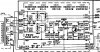
Here's the schematic for the power supply board. It shows all the voltages and the jumper numbers I mentioned.

Good job of systematic troubleshooting @runningdog, keep going. Just to make sure we are on the same page, @buzzclip, are speakers connected and Main speaker button pressed in and Tape Mon not pressed in? Also, any sound through headphone jack and other selector inputs (AM, FM, Phone, Tape, etc)? One last thing, do your speakers have fuses that might have blown with the short?
Side note: I mentioned visually checking to see if the relay is closing. Your 2220B may have a relay with a translucent cover, making it hard to see inside. This is the Omron LC2 N relay. The other relay used was clear, the Omron MY2-02. This only matters if you are replacing the relay, which would best be done after the no sound issue is resolved.
Hey guys. I'm so grateful for all the advice and quick replies. I can't wait to start tinkering again when I get home from work. I do have a dim bulb tester from when I restored my 2275. I'll make sure to use it while working on this. Off the top of my head, I know the relay is translucent so I'm guessing it's an Omron LC2 N. My speakers don't have fuses and are currently working fine with my 2275. They are 6ohm though, but the 2220b should be able to handle it. I'm sure the speakers were pushed on and the tape monitor was off. None of the other inputs worked either. I'll check the headphone jack. I honestly don't think I even have a 1/4" adapter anymore, but I'm sure I can pick one up somewhere. I'll keep you updated when I have a minute to open it up again and check voltage going from the power supply. Thanks again.