• The move to the new server is done. There are some software and database maintenance updates in process. This has us passing the hat around to help out. We appreciate any donations. Seriously, even a dollar helps. The payment page may be found here - https://www.audiokarma.org/support.html

2230 Idle Current

Richas

Member
While I wait for parts to fix my left channel amp board, I thought I’d check the adjustments on my right channel. I started with idle current. Volt meter in Millivolt mode across R774. Meter reads .2 mV. Adjusting R765 makes no difference. No speaker connected, volume all the way down.

Now R765 is in an unknown position…

What am I missing?

Rich
 
Register to hide this ad
While I wait for parts to fix my left channel amp board, I thought I’d check the adjustments on my right channel. I started with idle current. Volt meter in Millivolt mode across R774. Meter reads .2 mV. Adjusting R765 makes no difference. No speaker connected, volume all the way down.

Now R765 is in an unknown position…

What am I missing?

Rich
I think I’m gonna hold off on pursuing this right now. I’m going to rebuild this amp later and we’ll see how it adjust then.

Thanks
Rich.
 
OK I lied, still looking at this. ;-)

I think the Varistor mounted to the heatsink may be an issue. The schematic shows this as two diodes in series. Measuring with VMM in diode mode it is 0V either direction. Measures 0 ohm resistance.

The other channel varistor measures open in one direction and 1.3V in the other which seems reasonable.

Assuming the first is bad what can I use as a replacement? It looks like these are not available.

Rich
 
I replaced the bad H006 varistor with two 1n4148 diodes in series. I am now able to adjust the bias normally.
I’ll have to come up with a good substitute for that varistor, there’s lots of posts about this here.

Rich
 
Now I am fixing the left amp which had two cooked resistors and the driver transistors tested bad and the output transistors were cooked.
I have replaced:
The output transistors
All the other transistors:
H751 was 2sc945 it got ksc945
H752 was 2sc960 it got 2n3440
H753 was 2sc371y it got ksc1815
H754 was 2sa562 it got 2n3906 (I swapped the BC legs)
H755 was 2sc959 it got 2n3440
H756 was 2sa606 it got 2n5415

Electrolytics replaced
trim pots replaced

Brought it up slowly on a varian with dim bulb and we have sound!

But, alas, I am unable to get the bias voltage above 2mV.
The H006 varistor tests ok, 1.3V forward, 0v reverse.
The amp has the thermistor with series resistor mod for H757.

Any ideas?

Rich
Solved it, I still had the dim bulb on the line voltage.

Who's the real dim bulb here? ;-)

Rich
 
Not out of the woods with the left amp section yet. The clipping adjustment would not even out the clipping levels. I tracked it down to a 220 ohm resistor that was replaced with a 2.2 ohm resistor. I thought I checked them but I must have just seen red red what? This receiver is the proverbial can of worms.

Rich
 
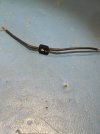
Rebuilt with varistor. Epoxy filed down.
 

Attachments

  • IMG_9925.jpeg
    IMG_9925.jpeg
    85 KB · Views: 9
  • IMG_9926.jpeg
    IMG_9926.jpeg
    79.5 KB · Views: 9
  • IMG_9931.jpeg
    IMG_9931.jpeg
    135 KB · Views: 9
Back
Top Bottom