• The move to the new server is done. There are some software and database maintenance updates in process. This has us passing the hat around to help out. We appreciate any donations. Seriously, even a dollar helps. The payment page may be found here - https://www.audiokarma.org/support.html

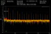
2230 with high distortion

runningdog

AK Subscriber
Subscriber
I have a newly rebuilt 2230. It is a clean receiver and the rebuild went smoothly. Until distortion testing. The Total Harmonic Distortion measures high in both channels. The spec calls for <0.5% THD. This receiver exceeds that by the time it is putting out 2 volts per channel. At 15.5v (30w) it is hitting 1.6% THD.

After double-checking the bias and clipping settings, I tested to see if the distortion is on the "pre" or "main" side of the receiver. When the Pre Out jacks are fed to another amplifier, the distortion is not there. But if a pre amp is connected to the Main In jacks, the distortion appears. So it appears to be limited to the "main" side of this 2230.

I'm trying to understand why it is in both channels. Is there something the main amps share in common I should be looking at? The wire pair from the transformer, the rectifier, or the big capacitor? And of course I could have made identical mistakes on both main amps when rebuilding them. My posts here too often come down to some mistake I made. Heh.

Your suggestions will be appreciated.

-Randy
2230 with high THD.png
 
Register to hide this ad
I wonder if you installed an electrolytic capacitor backwards on both amps. IIRC, there is one (C754?) that is marked wrong on some boards, see M-2230-1.

Tom
 

Attachments

I wonder if you installed an electrolytic capacitor backwards on both amps.
Heh. I wondered too. But all the new caps are in correctly. The other part replaced on both amps is the diode at H757. I used a 1N4148.

I'm bench testing the amplifiers independent of the chassis. But I've only done this with direct coupled (2245/2270/2325 etc) amps. Does a 2230 amplifier require the coupling capacitor be in the circuit. I assume it does but I'll risk asking anyway. What about the resistor going to the output lead? Does this also need to be included in a bench test?

I can get only about 5v output from the amp when powered with my bench power supply but the distortion was showing up below that level before. Low distortion measurements on the first amp tested. Next up is the other amp. If both test fine, then I'll start to jumper them back into the chassis and see when the distortion returns.

2230 main amp bench test_resize.jpg 2230 main amp output resistor_resize.jpg
 
I have used 1N4148/1N4448 for H757 with no issues.
When bench testing capacitive coupled output amps, you should provide a coupling capacitor between the amp output terminal and the load. Did you notice that the speaker side of the output coupling capacitor is connected back to a Zobel netwrk (R77/C760) on the amp board?
From the graph you provided, I wonder if you are somehow overloading your measurement device with either the audio signal or DC.

Tom
 
The issue is resolved. I think Tom had it right with "somehow overloading your measurement device with either the audio signal or DC". What was puzzling to me was why both amps?

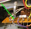
What: Jumpers J762 were loose on both amp boards. When mounted in the chassis the connections to the boards were broken.

Fix: I jumpered J762 to J764 on both boards.

How: J762 has a grounding strap. I left it attached to the chassis when I rebuilt each board. The board was being moved around and the pressure on J762 broke them loose. My bad.

2230 main amp J762 grounding strap_resize.jpg
 
The issue is resolved. I think Tom had it right with "somehow overloading your measurement device with either the audio signal or DC". What was puzzling to me was why both amps?

What: Jumpers J762 were loose on both amp boards. When mounted in the chassis the connections to the boards were broken.

Fix: I jumpered J762 to J764 on both boards.

How: J762 has a grounding strap. I left it attached to the chassis when I rebuilt each board. The board was being moved around and the pressure on J762 broke them loose. My bad.

View attachment 1322836
Good eye!!!!
 
Good catch! :thumbsup: Even when unscrewed from the chassis those metal tabs tend to catch on things and I’ve seen more than one with cracked/broken solder. The last few I’ve just proactively replaced them with wire and consider it an upgrade.
 
I have a newly rebuilt 2230. It is a clean receiver and the rebuild went smoothly. Until distortion testing. The Total Harmonic Distortion measures high in both channels. The spec calls for <0.5% THD. This receiver exceeds that by the time it is putting out 2 volts per channel. At 15.5v (30w) it is hitting 1.6% THD.

After double-checking the bias and clipping settings, I tested to see if the distortion is on the "pre" or "main" side of the receiver. When the Pre Out jacks are fed to another amplifier, the distortion is not there. But if a pre amp is connected to the Main In jacks, the distortion appears. So it appears to be limited to the "main" side of this 2230.

I'm trying to understand why it is in both channels. Is there something the main amps share in common I should be looking at? The wire pair from the transformer, the rectifier, or the big capacitor? And of course I could have made identical mistakes on both main amps when rebuilding them. My posts here too often come down to some mistake I made. Heh.

Your suggestions will be appreciated.

-Randy
View attachment 1320698

I’m just curious what analyzer you are using? And can you post a printout of the THD after problem solved.
Pretty cool test result you posted
 
It’s a Quantasylum QA401. I know because this thread caused me to research it and eventually get Santa to buy me one for Christmas. Randy helped me a lot by answering questions about it. Can’t wait to dig into it and learn how to use it after Christmas. :biggrin:
 
Mark from Blueglow Electronics had a short segment on this unit. I think he either bought one or got one for evaluation but I have yet to see the tests.
 
Mark from Blueglow Electronics had a short segment on this unit. I think he either bought one or got one for evaluation but I have yet to see the tests.
I read everything I could find on it, and most feedback was very positive. It has a built in low distortion signal generator and very comprehensive software. One limitation concerned me. It has an input voltage limit of 26v peak to peak, although it has robust protection if input voltage should exceed that. Of course, it will exceed that with higher powered audio amps. But Randy showed me how he uses pairs of 5.6k ohm, 5W resistors to make a voltage divider at the speaker terminals to cut the voltage in half. You can divide it more than once if needed. This makes it useful for all amps. I looked for a long time at used Keithly and HP analyzers. But their complexity + age made me concerned about reliability and accuracy. I decided to go this route to get the advantage of new components and upgradability as the software evolves.
 
I’m just curious what analyzer you are using? And can you post a printout of the THD after problem solved.

As Steve said, a QuantAsylum QA401. Here are the before and after results on the 2230:

2230 Guy S with high distortion.png 2230 Guy S after fix.png

This next one shows how it responded to one corner being lifted, before fixing it:
2230 Guy S when corner lifted.png

You can see how the noise in both channels shot up.

The display shows issues that I do not always hear. For example, you know how a 2325 nearly always has a hum when the bottom cover is off? That additional noise shows up in the display, even when it is not necessarily significantly affecting THD. So I get visual confirmation when the cover is back on that the hum is gone.
 
Back
Top Bottom