
• The move to the new server is done. There are some software and database maintenance updates in process. This has us passing the hat around to help out. We appreciate any donations. Seriously, even a dollar helps. The payment page may be found here - https://www.audiokarma.org/support.html

2245: -35v DC at output

kasbah512

Member
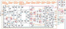
So after resolving some other issues, I'm now seeing -35V at J756. Here's the components I've tested so far and they all are functioning correctly: H002, H751, H752, H753, H755, H757, H759, H760, H761, H767
I'm not really sure where else to look, or if i should even bother checking the + side. I am getting the correct voltages at J753 & J761, and its not coming from a short in the protection circuit. The original issue was a failing open fuse from corrosion. not shorted, but it had very high resistance.
 

Attachments

  • Screenshot from 2024-01-15 20-02-33.png
    Screenshot from 2024-01-15 20-02-33.png
    243.9 KB · Views: 21
Register to hide this ad
Pull both Output Transistors and then recheck the voltages. One may be shorted.
Maybe my understanding is flawed, but if H001 was shorted, why would i be getting negative voltage? I already checked H002.

Edit: H001 is PNP, same as H003. H002 & H004 are NPN.
 
Last edited:
Did you double check the trace side for any shorts, solder bridges, etc?

I've had a problem I couldn't find after a few visual inspections but once I removed the flux from between some solder joints it then worked fine. Just couldn't see it being as small as it was.
 
Did you double check the trace side for any shorts, solder bridges, etc?

I've had a problem I couldn't find after a few visual inspections but once I removed the flux from between some solder joints it then worked fine. Just couldn't see it being as small as it was.
I've looked fairly thoroughly. There are only two electrolytics on this board. While the joints aren't pretty, they aren't creating a bridge. They have also since been touched up. It was returned to the shop I work with by a customer, for distortion and an eventually tripping relay. (I have no idea who worked on it before, but there was no evidence of other components being removed) The original issue I found was the that two fuses were failing open. Not open, but with VERY high resistance. It was "fully functional," but started failing during the smoke test, and eventually ceased to allow the relay to engage. DC bias and offset were set prior. I'm guessing something was working too hard and eventually gave out. I'll pull it and try to check the other side for any funny business.
 
Maybe my understanding is flawed, but if H001 was shorted, why would i be getting negative voltage? I already checked H002.

Edit: H001 is PNP, same as H003. H002 & H004 are NPN.
My understanding gets flawed all the time, lol. I want to believe I can “cypher” my way to a resolution with brain power. And I’m usually humbled back to doing the basics that were rattling around in my head from the beginning. Few shortcuts in this work ever pay off, at least for me.

The reason you would get negative rail voltage with the failure on a NPN transducer is because the circuit is balanced between the +/- rails. If a NPN or other component on the Pos side shorts to ground, the entire circuit is now unbalanced to the Neg side. I hope my explanation makes sense and is valid. I am not a EE but have tried my best to learn over a few years.
 
My understanding gets flawed all the time, lol. I want to believe I can “cypher” my way to a resolution with brain power. And I’m usually humbled back to doing the basics that were rattling around in my head from the beginning. Few shortcuts in this work ever pay off, at least for me.

The reason you would get negative rail voltage with the failure on a NPN transducer is because the circuit is balanced between the +/- rails. If a NPN or other component on the Pos side shorts to ground, the entire circuit is now unbalanced to the Neg side. I hope my explanation makes sense and is valid. I am not a EE but have tried my best to learn over a few years.
Thats fair. Whatever it was, it's fine now. After completely removing the board and soldering jumpers/extensions to the power supply to get a better look, I realized i was getting full rail voltages at both bases for the outputs. + 39 V on the PNP base, and - 39 V on the NPN base. That would be worse than the typical short. HOWEVER, the schematic was incorrectly labled, and those were actually the emitters i was measuring. I did some more checking, and found the correct-ish voltage where the bases actually were. Everything was hooked back up, biased, and offset again. All is well.

The one thing that seems most likely is that frayed wires on the protection circuit were making contact with the -35 V with no more than a strand. Or, when I reconnected the outputs, the outputs harness were reversed. Im not sure about the latter. I feel like it would either instantly fry them, or nothing would happen at all. Im not sure yet, but I'll have to do some experiments to see.

I could definitely see that now, a short with a PNP. No voltage downstream to the positive side, and providing a difference in voltage to trigger the negative side.
 
I have had a leg of an output transistor miss the female pin and get wedged between it and the heatsink shorting it to ground. I’m much more careful ever since and don’t force the pins if I start to feel resistance.
 
Back
Top Bottom