• The move to the new server is done. There are some software and database maintenance updates in process. This has us passing the hat around to help out. We appreciate any donations. Seriously, even a dollar helps. The payment page may be found here - https://www.audiokarma.org/support.html

2245 P400 tone amplifier right channel not working

runningdog

AK Subscriber
Subscriber
The right channel of this 2245 P400 tone amplifier is not working. This after both channels were rebuilt with new caps and transistors. Here are some observations.

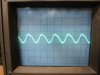
When powered up there is a clean signal for a second or two until the voltages rise past correct levels to these levels. The output of the board changes to a saw tooth then to a shark fin:
1 IMG_7952_resize.JPG 2 IMG_7957_resize.JPG 3 IMG_7954_resize.JPG


The right channel voltages are way off at H405 and H407. For example there is nearly 30V instead of 12.5V between the collector and base of H405 and H407. And H405 is getting insufficient voltage to turn on:
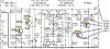
2245 P400 right channel schematic.jpg
.

All resistors have been compared between the right and left channels using an ohmmeter and a Huntron Tracker. All four transistors were replaced again just to be sure.

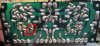
Here's the top and foil side of the board. The right channel is on the right when looking at the top, and on the left looking when at the foil side.

224 P400 component side_resize.JPG 2245 P400 foil side_resize.JPG

Thank you in advance for your thoughts on what to do next.
 
Register to hide this ad
I would start with cleaning all the flux between the traces. I couldn't bias a Sansui and found the tiniest solder bridge with a magnifier.
 
I know you may have done this but make sure they are proper PNP and NPN. I've misplaced them before but not sure if this was the effect.
 
Maybe the red circled solder joint needs more solder - as in Q407 base pin is not making contact.
Good catch. now that you mention I see some other places where a good reflow would be beneficial.
 
;
I would start with cleaning all the flux between the traces. I couldn't bias a Sansui and found the tiniest solder bridge with a magnifier.

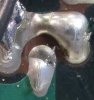
Always good advice and despite being certain of no bridges I found one. Could only see it in the magnified photo:
solder bridge.jpg

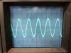
Randy and Otavio, good catches. After fixing the solder bridge I replaced all four transistors, checking to see that the placement matches the left channel. No change. I reflowed all of my solder joints. Now it works. WooHoo!

IMG_7980.JPG

Doing the photos was a good exercise. I'd get the solder joints to where they all looked good, but magnified not so much. Not wanting to display more crappy soldering I redid it until it looks reasonably good even in a photo.

This thread is another in a series that end with "Found my mistakes, thank you all for your help!"
 
I've been working on a 2270 that has had criminal butchery committed to it. Someone broke a lead off each STV diode. I redid one and epoxy fortified it, replaced 3 wires and fixed power filter cap mounting (one was totally loose and held in by the horrid common bus connection). I did the second amp yesterday and forgot to solder the nice small flexible wire I put on the second STV diode and powered up, slowly and as the bulb went dim, I hit the switch to bypass the bulb and in seconds had two smoking resistors! Amazingly they still measured spot on. Stuffed the wire into the board and soldered it and repeated the slow power up and had headphone audio. No outputs yet. Oops!

Just to relate that even experienced techs make boo-boos! Luckily, I had some nice correctly rated resistors in stock to fix that boo-boo. Going with higher wattage resistors would be a safety issue apparently!! :rflmao:
 
Back
Top Bottom