
• The move to the new server is done. There are some software and database maintenance updates in process. This has us passing the hat around to help out. We appreciate any donations. Seriously, even a dollar helps. The payment page may be found here - https://www.audiokarma.org/support.html

2245 Restore under way

misterguitar

Active Member
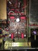
So I got a nice 2245. Its an early serial unit with the engraved face and everything. I pulled the phono board and decided to do a stem to stern rebuild. I gathered advice from the AK forum posts about caps and such. Decide to replace the trimmers, the caps, and all the old carbon comp resistors with new foil ones with tighter tolerances. Looks nice! But It doesn't work! Lesson learned.. Replace a few things at a time, test, replace a few more things. lol

It is getting 35 volts at 706. All the solder joints look good.I used Vishay Dale mil spec foil resistors. When they were available. I used I got a bunch of Toshiba SC2240BL transistors and used those to replace the H705 and H706. Caps where replaced . Used a Slimic 220 50v for C713. Used 47uf 50v for c703 and c704. Used WIMA 1uf 250v for C714,C715,C701,C702. All my subs sound ok I hope? Started poking around at the transistor voltages at 701 and 702. They seem off. I have kind of suspected that Mouser sent the wrong part for R734. It looked suspect. it was TINY compared to the other resistors. Maybe not enough wattage? I order it again just to see and they sent the same thing again.I measured the part with my meter. 100ohms. Just doesn;t look big enough wattage wise? Would that be a problem?
 

Attachments

  • IMG_0086.JPG
    IMG_0086.JPG
    80.2 KB · Views: 67
Register to hide this ad
I've also used components that were quite a bit smaller than the OEM's. As long as the measure OK and are spec'd at proper wattage, I'm going to say it's not a problem.

On the other hand, you'll want to change those blue drop tantalum caps, they seem to always drift and sometimes fail.

I also put new transistors in the 2230 I did the phono board on (also did a 2216, phono sections sound great, didn't really check voltages after rebuild).
 
You replaced the trimmers did you adjust these correctly and are they the right value. The 2 transistors did you check pin outs?
 
If the watt rating was wrong, the resistor would get real hot. Are you absolutely sure the resistors you used are the correct ohms.
Did you check each one as you took out to confirm the one your putting in is the correct value?

If in doubt, here is a picture you can get color codes off of. I stole it from a thread.
index.php
 
Yeah I tried adjusting the pots which didn't help. I'm going to pull the vishay dale numeric codes for these non banded resistors tonight to double check them. I did check the 2245's with my Tektronix DM253. I had bought like 20 of them and tested each for hFE and tried to match the two that where closest in value. I pulled the data sheet and check the board and they appear to be correct. Diodes are in the right orientation. Do these Wima film caps just take a while to break in? I'd use the signal generator to put a tone on the phono input, but my scope is down for the short term while i wait for my new 1x/10x probes to show up so I have no way to look at the output. The resistor R734 doe snot get hot. So I guess maybe it is correct. I powered it all up and checked the transistor voltages on the left channel. The right channel voltages where spot on with these so no point posting the same identical numbers.

H702 B .54v C 136mv E 36mv
H704 B 136mv C 12.17v E .64v
H706 B3.9v C 34v E 3.9v


as you can see none of these make sense! lol
 
I would add I've been reading and studying the Schuler Electronics Principals and applications book in an effort to get a better grasp on how these circuits actually work so I can get better at figuring this stuff out myself. :D
 
Does anybody know what wattage these trimmers are? 1/2 watt? I'm guessing wattage doesn't matter as long as it can handle the current.
 
I would put the old ones back in. Not going to gain much, if anything there. In my opinion anyway.
 
Just figured it out. trimmer is 1k ohm instead of 100k ohm. DOH! Ordered wrong part! No wonder it was so tiny!
The resistance value doesn't determine the size BTW. Pots are made in different sizes to fit different circuit boards and wattage requirements. I agree with Bryan and Pat, put the old ones back, they rarely get fussed with so are not worn out and I've never had an issue with these.

Wattage and current both matter in a pot's rating but mainly the wattage. Watts equate to heat and excess heat will kill the pot or any other part at some point.

On the resistor being smaller, that's a general indication that the wattage may be at a lower rating but not necessarily! The material used also is a part of what size/wattage rating a resistor may have.
 
... I did check the 2245's with my Tektronix DM253. I had bought like 20 of them and tested each for hFE and tried to match the two that where closest in value....

What are "2245's"? You don't need to Hfe match the transistors anywhere in the phono circuit either, nothing at all to gain here. (Get the pun?!):-)
 
My bad. I miscombobulated the transistor part number and model#! I would put the old ones back in but it appears the tin I had them set aside in was pitched by accident by my spouse thinking it was junk. That will learn' me for leaving "my mess laying out" as she would put it. ;) Should have my new correct resistance/size trimmers in my mail box in the next few days. So when working on the power supply board on these do folks usually work "in situ", or do they remove the baord? I have all new resistors for the board. When I pulled the resistors off the phono board a few where out of spec but not many. I am debating whther I want to go to that level of effort on the PS board as it looks like a lot more trouble to remove. I'm also not having fun with when the wire to something in the chasis is just the right length being able to get the old soldered end reconnected and looking nice. So not removing that board sounds like a good plan.
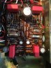
 
ok. So the power supply has been recaped and all new Kamaya 5% Carbon Comp resistors. As far as the power supply went a few resistors where off by more than tolerance, but not many. C805 was bulging read 6.13 instead of 3.3uf. C810 was reading 100uf instead of 47uf c803 was reading 584uf instead of 470uf. Needless to say a all but the big one where off by a good amount. Power supply is working well now. Got it set to 35 volts now. I did get the correct trimpots today from mouser and my phono board now has 100k trimmers instead of 1k trimmers. Unfortunately this did not help. My transistor voltages are still WAY off. I checked all the replaced resistor values. Everything lines up part number wise. So to troubleshoot would I start by taking voltages at H701 and 702? I can get those pretty close to what they should be if I adjust the trimmers.
 
Thanks for the picture! What I can see looks okay, the one dual diode string is covered in heatshrink so I can't tell. It looks like the pots are at one end stop which could screw things all up. Try centering them both and taking a listen again.
 
Yeah the diodes I put in the tubing just to make sure nothing shorted across them. The trimmers are brand new Bourns. I tried centering them and it affects the Base voltage at 701 and 702. But the collector voltage is like 27.2 volts! (sounds like something is seriously wrong!) I'm just learning about amplifier circuits so I'm trying to use this as a learning tool to pick apart what's wrong here. This looks like a common emitter type amplifier?
 
Hopefully someone can help, we're out of town all weekend. Good on you learning electronics!
 
Back
Top Bottom