• The move to the new server is done. There are some software and database maintenance updates in process. This has us passing the hat around to help out. We appreciate any donations. Seriously, even a dollar helps. The payment page may be found here - https://www.audiokarma.org/support.html

2270 - Flickering stereo due to noise

ocdecio

The proof of the restoring is in the listening.
Subscriber
This is another case of FM stereo on a 2270 that I've not seen before. From what I could measure, the noise detection circuit is preventing stereo from holding - it flickers once in a while and it follows the noise signal at J555.

I am wondering if a noisy transistor in the IF section could cause this? I can actually hear some crackling noise in the background as this is happening.

Or would this be due more to alignment issues?
 
Register to hide this ad
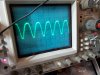
Here's the carrier signal at the end of P200. It doesn't look very symmetrical and I believe it should be

.20220925_071632.jpg
 
There are so many reasons why a 2270 tuner can't lock onto a stereo signal. In my experience, it is most often a weak signal -- that could be inadequate antenna, dirty contact in the attenuator switch, broken wire in the antenna circuit, or a problem in the front end section. The easiest way to check this is with a spare front end subbed in for the one in the tuner. Without that or equipment for measuring the RF signal, it is a lot of guesswork. If you start your testing at the back end of the circuit and are not getting stereo, you just have no idea if the problem started at the front or if one of the intermediate boards has a problem. I have spent a lot of time chasing my tail around the P550 and P300 boards only to find the problem near the front. This one may not work out that way, but just something to think about. What kind of signal strength are you getting on your signal strength meter when tuned to a strong station?
 
Last edited:
Here's the carrier signal at the end of P200. It doesn't look very symmetrical and I believe it should be

.View attachment 2672937
Great advice by Steven above.

This is very typical looking to me. I am thinking it may be noise from dried out grease at the air cap bearing points. That is where the shaft that has the moving fins sits. A light amount of DeOxitD5 can help or a small drop of synthetic oil at each point. If the DeOxit gets on the circuitry it will throw it off tune for a few days until the carrier liquid dries out.

Just went to war with a 115 tuner with no stereo and low signal strength and finally found a bad 0.1uF ceramic cap at the 4th IF stage (P200). Found it by pumping up the common rectified voltage bus that is fed by each stage with a resistor sub box and the +13V supply. That would make it jump up and stay for a bit at the affected stage. Yep, poked around the same complement of boards as Steven!
 
Great advice by Steven above.

This is very typical looking to me. I am thinking it may be noise from dried out grease at the air cap bearing points. That is where the shaft that has the moving fins sits. A light amount of DeOxitD5 can help or a small drop of synthetic oil at each point. If the DeOxit gets on the circuitry it will throw it off tune for a few days until the carrier liquid dries out.

Just went to war with a 115 tuner with no stereo and low signal strength and finally found a bad 0.1uF ceramic cap at the 4th IF stage (P200). Found it by pumping up the common rectified voltage bus that is fed by each stage with a resistor sub box and the +13V supply. That would make it jump up and stay for a bit at the affected stage. Yep, poked around the same complement of boards as Steven!
I'll try the Deoxit. I actually see a good amount of strenght so that shouldn't be the issue but there is a fair amount of noise that sometimes can be actually heard.
 
Signal strength does look decent on the video. Since it is the tuning meter that is bouncing around, it makes me wonder about the discriminator circuit. Are you getting voltage bouncing at the discriminator diodes H503 and H504? If so, maybe either the H501 integrated circuit chip or L501 discriminator transformer? Or maybe one of the diodes? I would start measuring at the diodes on a strong station, and if voltage is bouncing, move back in the circuit until I find a stable point.
 
Signal strength does look decent on the video. Since it is the tuning meter that is bouncing around, it makes me wonder about the discriminator circuit. Are you getting voltage bouncing at the discriminator diodes H503 and H504? If so, maybe either the H501 integrated circuit chip or L501 discriminator transformer? Or maybe one of the diodes? I would start measuring at the diodes on a strong station, and if voltage is bouncing, move back in the circuit until I find a stable point.
Let me check that thank you!
 
Did anyone ever find a replacement for NJ703W? I can't even find a proper datasheet for it. I see similar LM703 and uA703 out there, not sure if these can be used. I am seeing distortion and noise on pin 2, whereas the input to the board is reasonably clean.

Another possibility - would a 2245 P500 work on a 2270? The boards seem to be pin compatible.
 
Interesting. I thought they were identical, but they are not. They are so close that it wouldn't surprise me if they were interchangeable. They do have a different IC at H501, and some of the pin numbering is different. But the traces are mostly identical. It might be worth a try if you have the 2245 board on hand.
 
The 2245 schematic shows J508 and J509 disconnected which doesn't seem to make sense - would anyone have a picture of an installed 2245 P500?
 
Thank you! It looks like not connected to anything and now that I mentioned I can see that the same happens in the 2270.

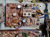
20220928_124302.jpg
 
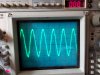
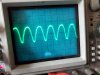
Just for the record, I doubt the issue is with the P500. It so happens that I had a spare, working and restored 2270 so I checked the input and output of the IC and the waves are exactly the same as the ones in the defective one. The waves "jump" in the latter and the stereo flickers at the same time.


20220928_132000.jpg 20220928_132018.jpg
 
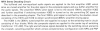
Sounds like you should be looking at the MPX Stereo Decoding circuit on P300. You can check to see if the 19kHz pilot signal is there at the input (from the P500) and follow it through the circuit. There is a transistor H303 that needs to be turned on to go to the doubler circuit to get the 38kHz signal. See description from the SM.

upload_2022-9-28_13-21-14.png
upload_2022-9-28_13-21-59.png
 
Back
Top Bottom