• The move to the new server is done. There are some software and database maintenance updates in process. This has us passing the hat around to help out. We appreciate any donations. Seriously, even a dollar helps. The payment page may be found here - https://www.audiokarma.org/support.html

2275: broken J708 wire on P700 board

JLS

New Member
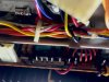
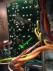
Just picked up a 2275 and am in the process of recapping (first attempt) and while working on the P700 power amp board the white wire that connects to the J708 pin snapped off. I removed the remaining wound up wire.

Before I noticed it after my recap, I was testing and there was no output. Now assuming this is why. What's the best way to reattach? Do I need a new wire or can I solder this end to the pin? What's the best approach? Pics attached.
IMG_3443.jpgIMG_3445.jpg
 
Register to hide this ad
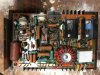
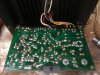
I've soldered it to the back of the board and still don't have output. Could be my (amateur) soldering job? I've included photos to identify potential trouble spots.

I am trying to solve a larger issue which is that when the P700 board contacts are unplugged, the signal is hot and crackles and pops when turning the volume and is only coming out of the left speaker. This is via AM, FM, and AUX. Same with the Remote outputs. When the contacts are plugged back in, there is no sound out of the unit at all. When I got it, the left speaker was dominant, but the signal was not popping or crackling with volume adjustment.

Here is everything done to the machine so far:
1) Deoxit on all push buttons, knobs, and outputs.
2) Recapped the tone board, power supply, and right power amp.

What are some things I should look for?
IMG_3470.jpgIMG_3472.jpg
 
Check to see if the relay is closing when you have just one amp plugged in. The relay is part of a protection circuit that will not allow the signal to reach the speakers if the amplifier is outputting high DC voltage. The relay affects both channels. So if the right amp is keeping the relay from closing, then the left channel does not play either. If the left amp has an issue keeping the relay from closing, then the right amp will not play either.

1. Unplug both plugs from the right amplifier, and leave the left plugged in. Does the relay click, and is there sound?
2. Unplug both plugs from the left amplifier, and leave the right plugged in. Does the relay click, and is there sound?

If the relay closes and there is sound when just one of the amps is unplugged then that tells you which amp is causing the protection circuit to leave the relay open, blocking the signal from reaching the speakers. Now there could be issues with both amps, but this test will tell which is causing the relay to remain open.

One connector to the amp, the one with 5 pins but only 4 wires, provides the power to, and the output from, the amplifier. The connector with 3 pins, is the input to the main amp.You'll notice it connects directly to the Main In jacks on the rear panel.

This is a good time to build a Dim Bulb Tester and to start plugging in the receiver to it. If you do not have one, you can Google Dim Bulb Tester and you will find many descriptions of how to make one. With a DBT, the current from the wall plug to the receiver passes through an incandescent light bulb. If there is a short in either amplifier, the DBT will light up rather than the fuse blowing. A 100 watt bulb will work if you still have them. Else a 75w will still do the job.

If one amp works when plugged in but crackles and snaps then that is an additional issue. We can do some more troubleshooting to see if the pops and crackles are coming from the amp, or from the preamp.

One additional test: If one amp turns out to be working but has crackles and snaps, use a pair of RCA cables to connect the Pre Out jacks to the Main In jacks. This will rule out the switches behind those jacks as the cause.
 
Thanks runningdog for the contextual information and advice. Very helpful for a newbie! I ran the test and here is what I learned:
  • R amp unplugged & the L amp plugged: relay clicks with sound (crackly) in the L speaker
  • L amp unplugged & R amp plugged: relay does not click. No sound in either speaker.
  • L & R amp plugged in: relay does not click. No sound in either speaker.
  • I made the DBT. With a 75w bulb, the unit powered on and dimmed the bulb with both combinations above. The bulb dimmed but didn’t go “out”. Not sure if that matters.
  • Plugged the Pre Out jacks into the Main In jacks and still experiencing the same issue.
I’d love to hear ideas for next steps to test.
 
Thanks for the clearly described test results, and that's great you made a DBT. If after you power up the receive the bulb just barely is on, then that likely is because it is a 75w bulb, where a 100w bulb would stay dark. The more power the receiver has, the higher wattage bulb needed. For example, the 125wpc 2325 keeps a 100w bulb dimly lit because it draws so much current at idle. Where a 125w bulb would be dark.

You've found:
The right amp has a significant issue, enough that the protection circuit is saying no way, dude.
The left amp is "good" as far as the protection circuit goes. The crackling could be the amp, but it could be almost anywhere in the signal path from the input jacks all the way to the amp.

The two issues can be worked on separately. Let's start with the easier one, the left amp, since it is working. Connect it, and leave the right amp disconnected.

1. Plug a music player into the Main In jacks. Be sure the receiver is turned off when you do this. And make sure the volume control on the music player is turned all the way down. This is because the Main In jacks go directly to the amps, bypassing the volume control in the receiver. Once powered up again, slowly increase the volume on the music player. You are testing to see if the static is still present.

If it is not, then the issue is between the input jacks and and the Main In jacks. That includes most of the switches and controls on the front panel.
If the static is still present, then it is between the Main In jacks and the speaker terminals, which includes the main amp, main and remote speaker switches and the relay.

2. Do you have another receiver or amplifier you can use to test with? This test uses the 2275 as a preamplifier only, and uses the other receiver/amplifier as the main amp. Connect the Pre Out jacks to an input on the other receiver. Aux or Tape In jacks will work. Don't use the phono jack.The receiver that is now the main amps has to have speakers or at least headphones connected to it.

With everything powered off, connect a sound source to the 2275, whatever you usually use, like a CD player plugged into the Aux jacks. Turn the volume all the way down on the 2275. Power up the 2275 and the other unit. Slowly turn up the volume on the receiver that is now the main amp, let's say to the 12 o'clock position. Then start turning up the volume on the 2275. You are testing to see if the static is still present.

If it is present, then the static is originating between the input jacks and the Pre Out jacks. This includes the volume, balance, and tone controls. And especially it includes the Tape/monitor switch and the Mono switch, both problematic.

Let's see what results you get.

 
Conducted the test. Here are results:

1. IPad plugged directly into Main In jacks. Signal is clean in R speaker. No static.
2. Plugged a Preamp (NAD 1020A) into the Pre Out jacks from the Aux inputs on the NAD. Static IS present.

Something else to note. The tone controls haven’t been appearing to have any effect on the signal. At a low volume with a non-distorted signal when I might be able to hear a difference, none of the tones seem to change the signal much, so it makes sense that the trouble lies there.

I don’t have ready access to an oscilloscope but I do have a MultiMeter if that can help with the next round of testing.
 
Good work!

1. Now we know the issue is not between the Main In jacks and the speaker terminals, so the left main amplifier is OK. And the main amplifier is not the source of the static.
2. The second test confirms the static is coming from somewhere between the input jacks, and the Pre Out jacks. That covers a lot of possibilities so we will narrow it down further.
3. The 2275 has a Tone Mode switch. If it is set to 'Off', or whatever it actually says, then the tone controls are disabled. Full counter clockwise is off.

As an aside, does switching the Tone Mode from off to on and back again result in a terrible noise from the speaker? If so let me know. Separate issue. Probably.

The next test will isolate the static to the left channel or the right channel, before it reaches the Pre Out jacks. You already know that when the left amp (the good one) is hooked up on the left then you get static. Now take out the right amp, and replace it with the left amp. Um, I'd mark them discreetly "L" and "R" somehow so that you can tell the original position for each amp.

1. Hook up the 2275 Pre Outs to the NAD Aux inputs, and see if there is still static.If no static, then the issue is limited to the left channel, between the input jacks and the speaker terminals.

2. If there is static, cycle every switch and control while it is hooked up and playing. See if the static changes any when you are pushing buttons and turning knobs.
 
Ha. I didn’t realize that the tone mode switch turned the tone controls “off”. I don’t hear anything noticeable when switching the Tone Mode from off to on

1. Moved the left amp to the right side and hooked up the Pre Outs to the NAD Aux inputs and there is still static
2. No discernible difference with the static when pushing buttons and turning knobs.
 
So you've established that the static is in both channels, and it is originating before the signal gets to the Pre Out jacks.

This could point to the power supply being the source of the noise. The reason is that both channels on the PE01 preamplifier are powered from the single power supply. There is a component on the preamplifier board in common to both channels and that is the large capacitor where the power comes in to the board. Has that been replaced? I think it is CE39 but I have to check.

Is the static you are hearing still like "crackles and snaps"?

This is the point where I'd be using a signal generator at the inputs, and testing the inputs and outputs of the preamplifier with an oscilloscope to see if the static is coming from it. Or I would just plug in a known good PE01 to see if the static remains.

I'm going to need some help from someone else at this point as I'm not sure how to establish if the static is originating at the power supply. Or how to test the at the inputs and the outputs of the preamplifier without a signal generator and 'scope.
 
I did replace that capacitor on the PE01 board. Photos attached.

I would still describe the static as crackles, pops, and snaps. At low volume, the signal is quiet and clear but when it is increased, all low tones distort and dominate the sound. I don't know if AK allows audio files, but I could upload a sample.

I will ask some "heads" in my area who might have, or know someone who has, an oscilloscope.
 

Attachments

  • IMG_3441 (1).jpg
    IMG_3441 (1).jpg
    85.2 KB · Views: 33
  • IMG_3442 (1).jpg
    IMG_3442 (1).jpg
    99.1 KB · Views: 28
Soldering Issue?
As I hunt to borrow an oscilloscope (so far, no luck) should I be looking for something else on the unit? Could my soldering be causing this? It wasn't horrible, but it was my first time soldering on a board. I am pretty confident I replaced all the caps correctly (direction, voltage, mV). But maybe there are some bad solder joints? I also didn't remove all the old solder. Sometimes I did with a wick, but if the old cap came out without disturbing the old solder, I slid the new ones in and sealed it up using the old solder and some new if necessary.

Either way, I see that the forum allows video to be uploaded. I will shoot a video tomorrow that illustrates the sound to see if anyone who's seen similar issues before can offer ideas.
 
A bad solder joint is a possibility. You have not recapped the power supply have you? Not that I expect recapping it to resolve this, I'm asking to know if there has been any soldering done on it yet.
 
Please upload a hi-resolution picture of the foil side of the power supply board, as well as one or more from the top such that the orientation of all the caps can be seen.
 
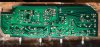
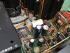
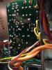
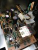
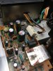
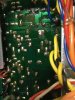
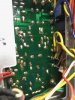
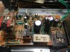
Here are some shots of both sides of the Power Supply board.

And here is a video illustrating the sound. First with an iPad in the Aux channel and then FM:
 

Attachments

  • IMG_3481.jpg
    IMG_3481.jpg
    97.5 KB · Views: 27
  • IMG_3485.jpg
    IMG_3485.jpg
    59.3 KB · Views: 28
  • IMG_3484.jpg
    IMG_3484.jpg
    61.2 KB · Views: 25
  • IMG_3483.jpg
    IMG_3483.jpg
    60.4 KB · Views: 25
  • IMG_3487.jpg
    IMG_3487.jpg
    63.4 KB · Views: 27
  • IMG_3486.jpg
    IMG_3486.jpg
    62.5 KB · Views: 25
  • IMG_3482.jpg
    IMG_3482.jpg
    101.6 KB · Views: 25
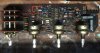
Reflow the solder on all of the solder joints for the capacitors added to the power supply. Remove then refresh the solder as needed.The attached picture points to one in particular.
IMG_3485.jpg
 
Back
Top Bottom