• The move to the new server is done. There are some software and database maintenance updates in process. This has us passing the hat around to help out. We appreciate any donations. Seriously, even a dollar helps. The payment page may be found here - https://www.audiokarma.org/support.html

2385 Tape 2 input is dead

richardg0n

Active Member
Hi Guys,
I have experience with restoring many 2325's and now have a 2385 that's my personal unit. I need to troubleshoot the tape 2 input. I can't get any sound out of it. Tape 1 works perfectly. Tried Deoxit on tape 2 contacts, and no sound, totally silent. Taking this guy apart to troubleshoot boards looks a little intimidating. How would you troubleshoot this?
 
Register to hide this ad
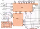
Unlike the Tape 1 input, Tape 2 also goes through the front panel dubbing jacks before going through the PS00 board (See diagram below).
  • Green and purple lines show the audio path of the Tape 1 input
  • Red and turquoise show the audio path of the Tape 2 input
  • It goes through the PV00 board and the 1/4" dubbing phone jacks have a self-shorting contact that connects the Tape 2 Input through the jack to the PS00 board
  • Make sure that these dubbing phone jacks are clean and making contact when no plug is inserted.
  • With power off, use your DMM check continuity from the L & R signals from the Tape 2 Input RCA jacks to the PS00 JS05 board pins 1 and 5.
  • If there is no continuity, then check the shorting contacts on the 1/4" phone jack
  • Another way to test this is to plug an audio source into the stereo 1/4" phone jack and see if you hear sound.
Screenshot 2026-04-30 170012.jpg
 
Wood cabinet? Seen problem with too long mounting screws shorting or messing up Tape 2 connectors on front panel (one of the front feet)
 
I believe it's if you used the wood cabinet screws without the wood cabinet, then they are too long. Remove the foot screw that is under the dubbing jacks and see if that solves your problem.
 
Unlike the Tape 1 input, Tape 2 also goes through the front panel dubbing jacks before going through the PS00 board (See diagram below).
  • Green and purple lines show the audio path of the Tape 1 input
  • Red and turquoise show the audio path of the Tape 2 input
  • It goes through the PV00 board and the 1/4" dubbing phone jacks have a self-shorting contact that connects the Tape 2 Input through the jack to the PS00 board
  • Make sure that these dubbing phone jacks are clean and making contact when no plug is inserted.
  • With power off, use your DMM check continuity from the L & R signals from the Tape 2 Input RCA jacks to the PS00 JS05 board pins 1 and 5.
  • If there is no continuity, then check the shorting contacts on the 1/4" phone jack
  • Another way to test this is to plug an audio source into the stereo 1/4" phone jack and see if you hear sound.
View attachment 3753029


Hi Dankik,
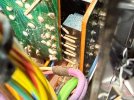
Thank you for the guidance. It looks like someone was previously in this unit and forgot to plug in PV00 to PS00(See Pic). Should I remove the front faceplate to reconnect?
 

Attachments

  • IMG_3193.JPG
    IMG_3193.JPG
    156.5 KB · Views: 8
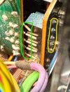
If you don't want to remove the faceplate, it might be possible to unsolder the 5-pin connector from the board (yellow), then straighten the pins on the mating board (green), plug the black connector into the straightened pins, then re-position the connector and re-solder the 5-pins into the board. Can you loosen the board with the pins to slightly move it back?

Or, maybe the other way around... unsolder the green pins, they might be individual pins vs a strip... unbend the one that are bent, insert them into the black connector then resolder the ends to the board. I can't see how the boards are mounted to the chassis.

Screenshot 2026-05-01 191525.jpg
 
If you don't want to remove the faceplate, it might be possible to unsolder the 5-pin connector from the board (yellow), then straighten the pins on the mating board (green), plug the black connector into the straightened pins, then re-position the connector and re-solder the 5-pins into the board. Can you loosen the board with the pins to slightly move it back?

Or, maybe the other way around... unsolder the green pins, they might be individual pins vs a strip... unbend the one that are bent, insert them into the black connector then resolder the ends to the board. I can't see how the boards are mounted to the chassis.

View attachment 3753652

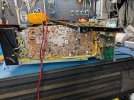
After removing the left-side metal plate and the switches/potentiometer selectors attached to PS00, I had some room to unsolder the 5-pin connector from the board (yellow). It's back together, and Tape 2 is now working. I'm going to create a new post because none of the unit's lights are working. Thank you Dankik!
 

Attachments

  • IMG_3211.JPG
    IMG_3211.JPG
    180.8 KB · Views: 4
Back
Top Bottom