• The move to the new server is done. There are some software and database maintenance updates in process. This has us passing the hat around to help out. We appreciate any donations. Seriously, even a dollar helps. The payment page may be found here - https://www.audiokarma.org/support.html

250M - ringing?

ocdecio

The proof of the restoring is in the listening.
Subscriber
Just finished repairing and restoring a 250M. While testing, I got same channels amplitude response to sinewave but when I test with a 15kHz square wave I am getting what seems to be ringing on right (top) channel:

RingingRight.jpg

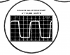
I'm wondering where should I start looking. It isn't bad but it is different enough between the two and definitely different than what the SM shows:
upload_2022-12-26_15-18-48.png
 
Register to hide this ad
It looks like minor overshoot to me. Is the waveforms above taken with X10 scope probes? If so, maybe the adjustment of the trimmer cap in the probe is off on that channel?
 
It looks like minor overshoot to me. Is the waveforms above taken with X10 scope probes? If so, maybe the adjustment of the trimmer cap in the probe is off on that channel?
Thank you, Randy! I am using simple mini-grabbers to BNC. I think you are correct, when I run the THD analyzer I get slightly higher (or isn't this slight?) distortion on the channel that overshoots. This is NOT at full power, just enough to get a result and some clue as to what may be going on. The three on the top are right channel (the one that overshoots) and the other is left channel.

One difference between the two - right channel doesn't have the original TO66 drivers, instead uses a pair of 2sc2334/2sa1011. I checked each small capacitor especially the Miller ones and they are OK. I wonder if there is anything I can do to bring the THD down to the other channel's level

THDWith300WLamp_18_14dbV.png
 
The different transistors probably have a lower capacitance on the base and may need a slightly larger Miller cap. Before you do that, set the generator to sine wave and for an output level of 1V p-p and increase the frequency from 1KHz on up, monitoring the output. At some point the output will fall. Keep increasing the frequency. The output should continue to drop until you can't see it. If it rises, the amp is unstable. If it just steadily decreases, it's fine.
 
The different transistors probably have a lower capacitance on the base and may need a slightly larger Miller cap. Before you do that, set the generator to sine wave and for an output level of 1V p-p and increase the frequency from 1KHz on up, monitoring the output. At some point the output will fall. Keep increasing the frequency. The output should continue to drop until you can't see it. If it rises, the amp is unstable. If it just steadily decreases, it's fine.
So I should continue way past 20kHz if I understand your instructions. This amp is spec'd to go up to 100kHz.

upload_2022-12-27_9-21-43.png

Thank you!
 
The different transistors probably have a lower capacitance on the base and may need a slightly larger Miller cap. Before you do that, set the generator to sine wave and for an output level of 1V p-p and increase the frequency from 1KHz on up, monitoring the output. At some point the output will fall. Keep increasing the frequency. The output should continue to drop until you can't see it. If it rises, the amp is unstable. If it just steadily decreases, it's fine.
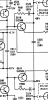
The Miller caps on these have a 10ohm resistor in series, wonder why.

upload_2022-12-27_9-55-52.png
 
The resistor limits the impedance to 10 Ohms.
Oh OK thank you. I tested and it went over 60Khz with a clean wave, same amplitude. It doesn't seem to be oscillating.

Should I try upping the 270pF?
 
Oh OK thank you. I tested and it went over 60Khz with a clean wave, same amplitude. It doesn't seem to be oscillating.

Should I try upping the 270pF?
You could try a 300pF or 330pF. Since we can't find a datasheet for the original part, we don't know what the Cob is, we can only try things.
 
You could try a 300pF or 330pF. Since we can't find a datasheet for the original part, we don't know what the Cob is, we can only try things.
Sounds like a plan. I'll then run the same square wave test and see if it makes any difference, if it doesn't I'll just keep it stock. You are correct, we have no idea what the original SJs specs look like.
 
Back
Top Bottom