• The move to the new server is done. There are some software and database maintenance updates in process. This has us passing the hat around to help out. We appreciate any donations. Seriously, even a dollar helps. The payment page may be found here - https://www.audiokarma.org/support.html

2SC458 as the bias transistor... replace?

JoshHendi

^ElectroNerd^
I am aware the 2SC458 has a bad reputation and is often cited as a 'replace on site' device.

I have a unit here (Yamaha CA-1000) that uses a 2SC458 as the bias transistor. I have no reason to believe it is bad, the bias circuits was operating correctly before this project began.

Should I consider replacing the 2SC458 here? If they were used in the signal path I would replace them, but wondering if their known issues would relate to bias duties
 
Register to hide this ad
Well, if a bias tr goes bad, bad things can happen.
Check if they have black leg disease. Replace if they do. I would replace them in any case.
 
I did a CR-800 and was able to put some shrink on the center leg and twist it around so the flat was on the flat.
 
  • Like
Reactions: mbz
What is the shape of the transistor? Aren't just the outhouse style the bad ones and later normal shaped one okay?
 
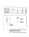
Yamaha service bullitine attached, provided by clinic-audio (IIRC?)

Only the LG type is problematic but still ok for temp compensation.
Using KSC1815 or... means round face to heatsink, not ideal. milo63's solution is a good one or retain the LG's for this purpose.
 

Attachments

  • 2SC458-page-01_2.JPG
    2SC458-page-01_2.JPG
    72.6 KB · Views: 24
  • 2SC458-page-02_2.JPG
    2SC458-page-02_2.JPG
    71.1 KB · Views: 23
Yamaha service bullitine attached, provided by clinic-audio (IIRC?)

Only the LG type is problematic but still ok for temp compensation.
Using KSC1815 or... means round face to heatsink, not ideal. milo63's solution is a good one or retain the LG's for this purpose.
Thank you for this doc/info! I've got a CA1k on the bench and another waiting in the wings, very useful
 
The best and most commonly recommended modern replacement for the noisy vintage 2SC458 transistor is the KSC1845.
I would replace it anyway. If you have to twist its legs to accommodate the flat side against the heatsink, do it.
 
I've got a CA1k on the bench and another waiting in the wings,
Very nice amp if you get the refurb right.
I hate doing that filter board, finding it best to unsolder both tone and filter boards. Disassembly and deep cleaning of all the switches is a real PITA but necessary, probably give similiar SQ improvements as replacing any caps...
 
i'm surprised that no one has ever filed down part of the round side to make it set flat in this situation.(or when making diff pairs)

we know leds can be filed down quite a bit if needed, are transistors similar in that way?
 
Are there any commonly available subs with an opposite pinout that would work for this?
So I went ahead and replaced the bias 2SC458s with KSC1815s...

I added a rubber cover on the middle leg of the 1815s, then held the base of the 3 legs and twisted the head of the transistor 180 degrees. This allows the flat part of the transistor to rest perfectly against the heatsink. There is barely enough leg length to get it soldered to the PCB and still have enough length to reach the pressure clamp, but it is possible and worked out great on this unit. Both channel's bias are perfectly stable and align great in both B & A modes
 
we know leds can be filed down quite a bit if needed, are transistors similar in that way?
based on the ones I've had explode, I can say there is usually a decent amount of plastic between the actual working bits and the outside. I don't think you'd ever get it to resemble the profile of the "outhouse" style but it could certainly have a flat put on it. Just not sure how much, may need some experimenting.

would be cooler if there was just some existing suitable device that just matched the pinout and then this wouldn't be an issue. Probably wouldn't mix them in a diff pair, that seems like a bad idea but for things like this it would be handy.
 
based on the ones I've had explode, I can say there is usually a decent amount of plastic between the actual working bits and the outside. I don't think you'd ever get it to resemble the profile of the "outhouse" style but it could certainly have a flat put on it. Just not sure how much, may need some experimenting.

would be cooler if there was just some existing suitable device that just matched the pinout and then this wouldn't be an issue. Probably wouldn't mix them in a diff pair, that seems like a bad idea but for things like this it would be handy.
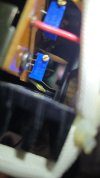
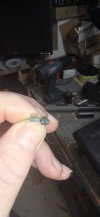
i couldn't resist

round sides are up. i just hummed it down with 80 grit, just like doing bodywork, i'd suggest stopping short and finishing in with 180 or 220 but i think it can be done.

no indication of die or wires

20261001_132859.jpg20261001_132906.jpg
 
huh, thats thinner than I'd have guessed, but nice to know that its an option. That would be nice to replace those dual transistor diff amps. Dab of glue or just heat shrink to bond them together and away you go.
 
Back
Top Bottom