Hi all. Just completed the mod for a 3000A with a kit from AfA on ebay. No issues installing everything, directions were very good but not understanding how to adjust the bias to get 0V offset, without affecting the bias, without affecting the offset. The directions just do not make sense to me.
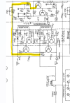
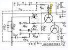
Currently, with the mod and all new mj21196 outputs (one channel was shorted), the bias set no problem at 80ma across the fuse holders doing the + and - simultaneously for each channel (btw, i also checked mv across the emitter resistors and all are 24-29 mv)...the trimmers look to be about the same position since when you raise one, the other raises, lower one, the other lowers, etc. so it seems that you could almost not even adjust one of them and still get 80ma so that's confusion point #1 for me. #2 is how do i adjust both at the same time while still getting 0V across the + rail emitter resistor?
My output voltages currently are:
L+ --> B,C,E: 2.1, 37, 1.5
L- --> B,C,E: -36.7, 1.5, -37
R+ --> B,C,E: -1.7, 37, -2.3
R- --> B,C,E: -36.5, -2.3, -37
The red emitter voltages after the new cluster caps is +1.4v for both channels, then with the 10 ohm resistor (or 8 ohm speakers), drops to 0V like every other cap coupled receiver i have worked on. So can someone do a sanity check for me here or advise what i need to do to get the red values to 0V or as close to 0 as possible, if possible? I have triple checked everything and would expect much different results if i had a bad solder joint or component installed incorrectly. it seems it all starts at the 25V of the smaller transformer primary, the two channels are about 1.5V difference. nothing is getting overly hot or anything, and unit sounds fine.
any help or guidance is appreciated. thanks.
Currently, with the mod and all new mj21196 outputs (one channel was shorted), the bias set no problem at 80ma across the fuse holders doing the + and - simultaneously for each channel (btw, i also checked mv across the emitter resistors and all are 24-29 mv)...the trimmers look to be about the same position since when you raise one, the other raises, lower one, the other lowers, etc. so it seems that you could almost not even adjust one of them and still get 80ma so that's confusion point #1 for me. #2 is how do i adjust both at the same time while still getting 0V across the + rail emitter resistor?
My output voltages currently are:
L+ --> B,C,E: 2.1, 37, 1.5
L- --> B,C,E: -36.7, 1.5, -37
R+ --> B,C,E: -1.7, 37, -2.3
R- --> B,C,E: -36.5, -2.3, -37
The red emitter voltages after the new cluster caps is +1.4v for both channels, then with the 10 ohm resistor (or 8 ohm speakers), drops to 0V like every other cap coupled receiver i have worked on. So can someone do a sanity check for me here or advise what i need to do to get the red values to 0V or as close to 0 as possible, if possible? I have triple checked everything and would expect much different results if i had a bad solder joint or component installed incorrectly. it seems it all starts at the 25V of the smaller transformer primary, the two channels are about 1.5V difference. nothing is getting overly hot or anything, and unit sounds fine.
any help or guidance is appreciated. thanks.