• The move to the new server is done. There are some software and database maintenance updates in process. This has us passing the hat around to help out. We appreciate any donations. Seriously, even a dollar helps. The payment page may be found here - https://www.audiokarma.org/support.html

300B filaments question

Selmerdave

AK Subscriber
Subscriber
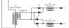
I built the below circuit which is meant to be based on Paul Joppa's idea of common-mode choke filtering from a 6.3V supply. In one post he mentioned using the Hammond 155B, 6mH/2A/0.3ohms. I used 50V/5A Schottkys.

I'm only getting 4.1VDC out, unloaded was 5.7V. I don't know how to model or calculate this, did I do something wrong or is this unlikely to work?
Screenshot_20220827-210417_Drive.jpg
 
Register to hide this ad
I built the below circuit which is meant to be based on Paul Joppa's idea of common-mode choke filtering from a 6.3V supply. In one post he mentioned using the Hammond 155B, 6mH/2A/0.3ohms. I used 50V/5A Schottkys.

I'm only getting 4.1VDC out, unloaded was 5.7V. I don't know how to model or calculate this, did I do something wrong or is this unlikely to work?

View attachment 2649888

With a full wave bridge you've got approximately 1.4V lost to the diode junction voltage using silicon diodes. Try changing the diodes to Shottkey diodes and you might be able to get the voltage up. Also, where's the filter capacitor?
 
With a full wave bridge you've got approximately 1.4V lost to the diode junction voltage using silicon diodes. Try changing the diodes to Shottkey diodes and you might be able to get the voltage up. Also, where's the filter capacitor?

He is using Schottkys. But the missing filter capacitor is the key. ;-)

Selmerdave, it looks like you're getting choke-input voltage, or .9 of the secondary voltage, which is probably high, unloaded.

A caution that a 1.2A tranny is a little low in current capacity for full-wave bridge rectification providing 1.2A of current. Generally, for bridge operation, you want at least twice the needed current capacity. Add the cap and you'll probably get closer the 5V, but that little tranny may get pretty warm.
 
He is using Schottkys. But the missing filter capacitor is the key. ;-)

Selmerdave, it looks like you're getting choke-input voltage, or .9 of the secondary voltage, which is probably high, unloaded.

A caution that a 1.2A tranny is a little low in current capacity for full-wave bridge rectification providing 1.2A of current. Generally, for bridge operation, you want at least twice the needed current capacity. Add the cap and you'll probably get closer the 5V, but that little tranny may get pretty warm.
I think that must be it and I should have realized that. I had those on hand and thought, "1.2, perfect"... I'll either switch to AC or find more suitable 6.3 tranny. Thanks.

FWIW I didn't give much background but the idea of the circuit is DC without caps.
 
It's funny, I'm realizing that the other issue I have with this amp is that the heater voltages on the front end are a little high because the 6.3V secondary is rated 4A. The front end tubes draw less than an amp so I'm hopeful that if I just reverse the 6.3V sources I'll solve both problems at the same time... That would certainly be convenient.
 
I think that must be it and I should have realized that. I had those on hand and thought, "1.2, perfect"... I'll either switch to AC or find more suitable 6.3 tranny. Thanks.

FWIW I didn't give much background but the idea of the circuit is DC without caps.

Oh, interesting! Yeah, swapping in a higher-current 6.3 supply might solve the problem, the little Stancor is probably getting dragged down by the current draw. Interested to see how it works out!
 
So I tried reversing the 6.3V sources, with only modest improvement. Front-end heaters are now at 6.8V (down from 7.1), and 300B filaments are up to 4.4V (from 4.1V), with 1.1VAC measured across them. Still not all the way there so it looks like I'm going to need to add a cap or switch to AC heating and use some dropping resistors on the front end.
 
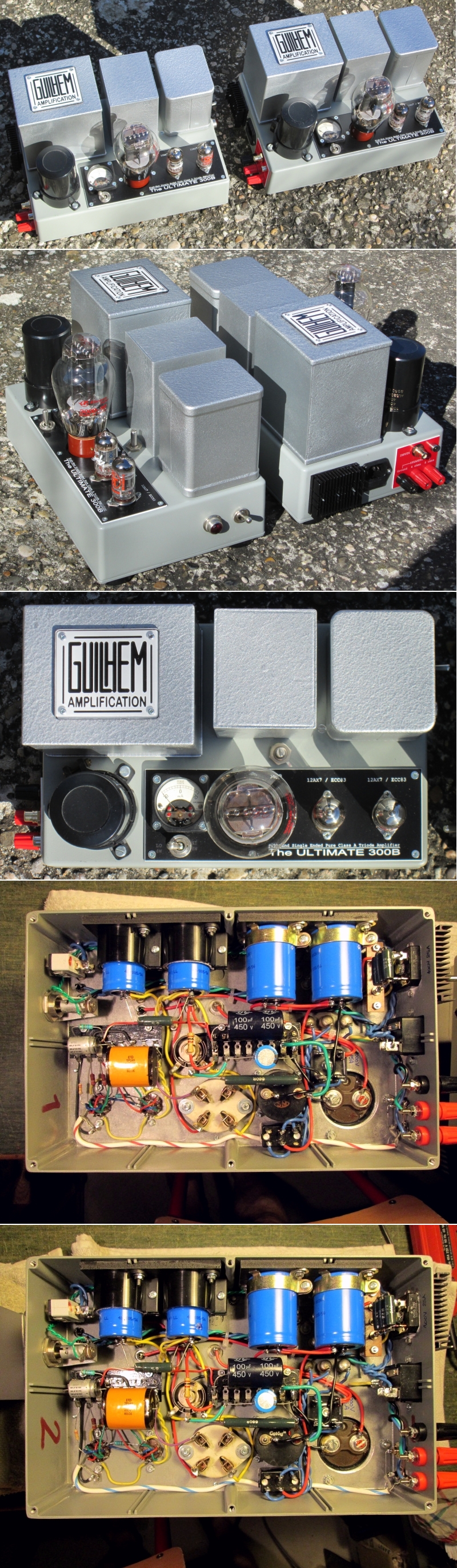
@Selmerdave : here is my solution ;) :

View attachment 2650101

I don't remember how much ripple I had across the 300B heater but it is a few dozen of mV peak to peak - I can retrieve the exact ripple value in my notes, though.

19102109190725019416472725.jpg


Cheers,

T
That's a nice looking build!!
 
I think Paul Joppa is one of the smartest tube designers around. He may have been talking about something else.
I don't see how he is getting common mode rejection using two separate chokes. Typically you use a choke with two windings of equal value on the same core, wound in opposite directions. The hum/noise is the common mode that is cancelled/rejected with the signals inverted relative to each other.
The idea with using the common mode choke instead of the CLC or CRC filter is that it doesn't adversely affect the sound which is noticeable with 300Bs in my experience.
 
Yes :
View attachment 2651355
And some don't like the sound of hum : me, among others. :no:
And 1µF is practically useless in reducing hum. :(

But it's me, OK ? :D

Cheers,

T
Paul Joppa was referring to using PSUD software ( https://www.duncanamps.com/psud2/ )which requires a cap in the schematic to get the program to calculate the results. His schematic shows a 10,000 uF cap after the common mode choke. He also indicates that a 1uF cap is "practically nothing"
Common mode chokes are very effective for reducing hum and noise. I don't know if you've ever tried them but you can get much lower than the 17.5mV you mentioned with a simpler circuit using a part that will last forever and sound better than large caps.
Also, in North America the hum will be 120Hz - not a big difference but it's there.
PSUD2 is very good for simulation power supplies and the results are very close to real world measurements. It saves a lot of time and is easier to learn than Spice.
 
Paul Joppa was referring to using PSUD software ( https://www.duncanamps.com/psud2/ )which requires a cap in the schematic to get the program to calculate the results. His schematic shows a 10,000 uF cap after the common mode choke. He also indicates that a 1uF cap is "practically nothing"
Common mode chokes are very effective for reducing hum and noise. I don't know if you've ever tried them but you can get much lower than the 17.5mV you mentioned with a simpler circuit using a part that will last forever and sound better than large caps.
Also, in North America the hum will be 120Hz - not a big difference but it's there.
PSUD2 is very good for simulation power supplies and the results are very close to real world measurements. It saves a lot of time and is easier to learn than Spice.

Any idea why my voltage is low? I actually hadn't seen that particular post linked above, I see he recommends high current Schottkys like 15-20A, maybe my 5A are too low?
 
It was used in a production amp for years, with no cap, so I'm not sure what the definition of "not working" is.
 
Without cap, common choke or not, it won't work, never :no:... Moreover for filtering the 1.2A/5V of a 300B ! Unless you decide to forget compactness and weight for your amp...:rflmao:

T

In the link above, Paul Joppa refers to one of their commercial products - the Paramount - which is a 300B amp that uses a common mode choke with no cap. I've heard one. It's very quiet and sounds great. 'nuff said.
If you are concerned about compactness and low weight, why are you using tube amps? Seems like a contradiction in terms.
As for simulators and software, welcome to the 21st century. They work, they're accurate and they're a much better use of time and money than endless prototyping. I did that before there were computers but these days I try not to waste time unnecessarily.
 
He's using a 7.6V transformer. That's likely the difference.
Oh wow, yes, that would seem to answer the question. I really thought I saw it with a 6.3V transformer but I wonder if I somehow misread it and went on planning around 6.3V. Thanks!
 
Without cap, common choke or not, it won't work, never :no:... Moreover for filtering the 1.2A/5V of a 300B ! Unless you decide to forget compactness and weight for your amp...:rflmao:

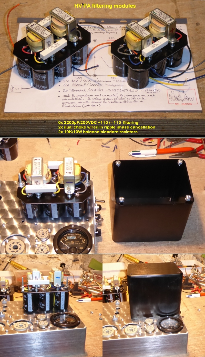
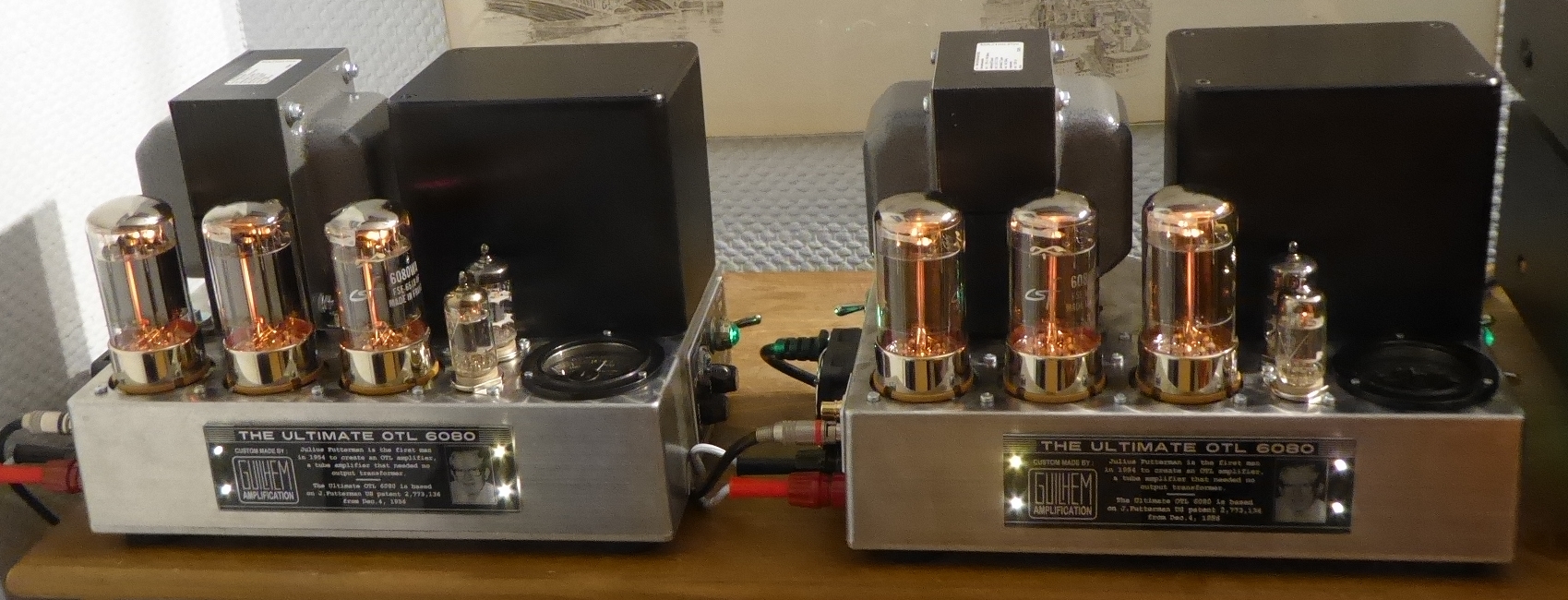
I used in my U-OTL amp a double common-mode choke to filter HV +115/-115VDC. It works fine, but the filter cap section totalizes 13200µF :

View attachment 2651727

Ml4SJb-modu2-06-07-2020.jpg


8bZXJb-P1100316.jpg


Now if you prefer to trust in Simulators and Smart Designers... Well... Go on ! :)

Cheers,

T
This will be my last comment in this thread.
Your schematic and the photos show two Hammond filament transformers, 266F12C, where the chokes would be. The photos also show where you have cut the brown, orange and white wires off, I can't see the black wire. Those wires are for the primary of those transformers so it seems that you are using the two secondary windings as pseudo-chokes. That's really not the same as using a common mode choke and could be why you didn't have good results without the caps. Even if you like the result, it doesn't indicate that you can discern the difference between the correct part for this application and a lash up that looks good in a hand sketch.
 
Back
Top Bottom