• The move to the new server is done. There are some software and database maintenance updates in process. This has us passing the hat around to help out. We appreciate any donations. Seriously, even a dollar helps. The payment page may be found here - https://www.audiokarma.org/support.html

300B tubes running cold

Dr. Humboldt

Active Member
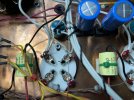
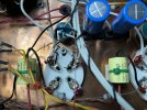
I'm a very happy owner of a used Dared SET 300B pair of 'quasi-monoblocks'. But neither of the 300B tubes get hot or glow red. And I mean they are room temperature to touch -- I had them on for about ten hours yesterday, checked them in complete darkness -- no glow or heat. I haven't opened the chassis: is there an obvious answer to this? Am I hurting my tubes or amp to run it like this?

The tubes are the JJ 300B's that came used with the amp.

Here are some stats from an audioreview.com, um, audio review:

Model: VP-300B QUASI-MONOBLOCK POWER AMPLIFIER (SINGLE-END CLASS A) TECHNICAL SPECIFICATIONS: MAX OUTPUT POWER: 6W FREQUENCY RESPONSE: 20-20KHz (±1.5dB) DISTORTION: =2% SIGNAL TO NOISE RATIO: =85dB INPUT SENSITIVITY: 350mV INPUT IMPEDANCE: 100K ohm OUTPUT IMPEDANCE: 4 ohm/8 ohm SIZE: L285 × W140 × H170 MM WEIGHT: 15.0Kgs/Pair THE TUBE USED: 12AU7x4,300BX2
 
Register to hide this ad
Thanks for the quick replies!

What does the person you got them from, say?

I bought them from a stranger on the big auction site a few months back -- I'll ask the seller.

Is it a multi-voltage version ? Can be set to European 230V so, all votages are down ?

I don't see a switch on the power supply, it has a sticker that says "AC 110 - 120 V", so I don't think that could be it.

I guess I should add that they sound good to my inexpert ears, powering Altec Model 17's.
 
300B filaments glows dark on my tube tester but moderately bright on my amp, if you don't even see in the dark, it's too dark, dangerous for the filaments to apply high voltages around. If you run them like this, they will not survive for long.

You must be very careful not killing yourself measuring voltages to the sockets point to check the filament voltage, i think the 300B must be 5V , corrects me if i am wrong.

Aligator clips to banana plugs leads can help to measure voltages from under the amp when he sit at his horizontal "normal" position, not to run tubes horizontally
 
Is it possible this amp is internally set to work with 2A3 tubes? You definitely need to break out the volt meter and measure between the two fat pins of the 300B, it should be 5.0V, either ac or dc
 
300B filaments glows dark on my tube tester but moderately bright on my amp, if you don't even see in the dark, it's too dark, dangerous for the filaments to apply high voltages around. If you run them like this, they will not survive for long.

You must be very careful not killing yourself measuring voltages to the sockets point to check the filament voltage, i think the 300B must be 5V , corrects me if i am wrong.

Aligator clips to banana plugs leads can help to measure voltages from under the amp when he sit at his horizontal "normal" position, not to run tubes horizontally

HO-ly resurrected zombie post, Batman!

My google-foo is weak, @mroboto, are you saying NOT running the heaters at specified voltage is BAD for the tubes?

I have this 20 year old Tektron 2A3/300b/50 amp that HUMS (120 Hz) when set at 5 VAC for 300b tubes, hum almost absent at 2.5 vac, so I’ve been running it for a few hours at the low voltage setting.

Bad idea?
 
My google-foo is weak, @mroboto, are you saying NOT running the heaters at specified voltage is BAD for the tubes?

I have this 20 year old Tektron 2A3/300b/50 amp that HUMS (120 Hz) when set at 5 VAC for 300b tubes, hum almost absent at 2.5 vac, so I’ve been running it for a few hours at the low voltage setting.

Bad idea?

Yes
+ or - 10%
More or less will severely shorten tube life.
 
One of my residency directors used to say (often enough we all got sick of hearing it): “The key to adult education is repetition.”

I have the spec sheet. I’ve READ the spec sheets.

I am NOT possessed of an eidetic memory.

Thank you again for the reinforcement. Seriously.

Back to the hum…

[oh, BTW: I’ve been running a set of EH 300b’s at the lower voltage, NOT the EML’s… seems my subconscious memory saved me there]
 
Does the amp have a hum pot for the 300B tubes? Have you got a schematic?

More info starting at post #80 here:
 
OK, that schematics very small to read the entire thing, but it does appear that it has an improperly implemented hum pot. The way it is implemented is guaranteed to hum eventually because all the current for the output tube plate goes through the wiper of the pot. Over time the pot gets noisy as resistance increases due to current where the wiper contacts the fixed resistor. I can't guarantee that is your problem as there is not enough information to go on. Does the hum pot have any influence on the hum?

The hum pot should be implemented as below with two resistors bypassing the wiper of the pot.

hum pot a.JPG
 
OK, that schematics very small to read the entire thing, but it does appear that it has an improperly implemented hum pot. The way it is implemented is guaranteed to hum eventually because all the current for the output tube plate goes through the wiper of the pot. Over time the pot gets noisy as resistance increases due to current where the wiper contacts the fixed resistor. I can't guarantee that is your problem as there is not enough information to go on. Does the hum pot have any influence on the hum?

The hum pot should be implemented as below with two resistors bypassing the wiper of the pot.

View attachment 3073215
Um, thanks, I think.

Yes, the pot DOES affect the hum - some - I adjust to lowest background 120 Hz hum.

I think the first sketch is right, according to your picture, but I’m not sure I’m seeing this right and I’ve been reading schematics since 1969.

The resistor at the bottom of your drawing should correspond to the paired blue bypass cap, right?

So should the result look like this:
1703794356058.jpeg

or this:

1703794386435.jpeg

Or maybe I’m a little caffeine-deficient at the moment..
 
Last edited:
One of my residency directors used to say (often enough we all got sick of hearing it): “The key to adult education is repetition.”

I have the spec sheet. I’ve READ the spec sheets.

I am NOT possessed of an eidetic memory.

Thank you again for the reinforcement. Seriously.

Back to the hum…

[oh, BTW: I’ve been running a set of EH 300b’s at the lower voltage, NOT the EML’s… seems my subconscious memory saved me there]
I had an eidetic (photographic) memory, but it never developed. As for the tube, check plate voltage and grid bias voltage to see if they are in spec. Be sure cathode has a connection to ground, either directly or through a resistor. Check the value of the cathode resistor if there is one. Be careful as you would be working around potentially lethal voltages.
 
I had an eidetic (photographic) memory, but it never developed. As for the tube, check plate voltage and grid bias voltage to see if they are in spec. Be sure cathode has a connection to ground, either directly or through a resistor. Check the value of the cathode resistor if there is one. Be careful as you would be working around potentially lethal voltages.

I’ve posted this elsewhere, or, deja vu, here before:
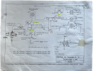
1703798212324.png

The portion of the circuit below the 5Z3 I haven’t unfolded yet, but it’s NOT in this amp, which predates this schematic by about 5 years, if the seller (local guy who
runs one of the annual HiFi shows in early December here in DC-MD), it was a dealer sample, without schematic, sounded AWESOME through a pair of Tannoy speakers (don’t know the model, but he mentioned a selling price of around $9k, IIRC) despite playing the original Sophia 2.5v 300b tubes at 5 VAC (I changed this later at home) without serial number, nothing signed inside or dated.

All capacitors check out okay (although I’ve bought replacements for the PS at the suggestion of a friend who works on tube amps - he bought my heathkit 1500 W Linear and MFJ 1000W HF amplifiers I had rebuilt so I might know my way around high voltage), thinking reducing ripple a little more might help - I haven’t gone there yet.

Okay, there is NO “stand by“ switch circuit, NO “pot per regulare la corrento della valvola finale” (potentiometer for regulating the current of the final output tube) also no “negativo di griglia” (negative feedback?) NOR is there a current meter, and the 1k 5% resistor/100 uF/200V cap precedes the hum pot on each side where I’ve sketched it in. The PS wiring is even more bizarre, and I’ve sketched it out twice, going to open this up again and take more photos for later review.

Voltages throughout seem in line with those on the schematic and published elsewhere (other 300b SET designs), a little high at the filaments of the 300b tubes - my notes showed 2.73 mV in one spot, another, second check showed higher. My notes are a mess - I need to do this over again.

As I’ve mentioned before, this was ALL the factory could supply, or would supply through their NA distributor.

From several different sources I hear:

1 - it’s an AC filament design, I’ll have hum (but I didn’t hear this when I bought it - might reconnect Ohm 4’s but I doubt this is the issue)
2 - run DC power to filaments - a little complicated, but doable, if only for 300b tubes, I can rewire later). I breadboarded Stephe‘s little 5 VDC circuit
and it runs CLEAN DC power at 5.01VDC with about 0.2 mVAC
3 - Buy better tubes (EMLs didn’t change this, why pay twice as much for WE 300b’s?)
4 - There shouldn’t BE any hum.

So, while I appreciate the help, I’ll likely just “deal with it” for now, finish building the Skunkie Designs amp I’ve got going and puzzle this out later.

Thanks again.

 
The bottom photo is correct. Remember: the object is to have the cathode current bypass the wiper of the pot to eliminate the noise created where the wiper contacts the fixed resistor. With a 100 ohm pot, there will therefor be very little adjustment for the hum pot since now most of the current will be taken by the two resistors. A proper hum pot would be a 50 OHM 2W CARBON LINEAR pot. A wire wound 2W linear pot would work as well. The reason to use a 50 ohm pot is to allow a greater range of hum reduction. In practice, however, there is generally very little adjustment needed. If this were my amp I would replace the pot and install the two resistors. Note the pot will be slightly larger in diameter than the existing one so it will be a tight fit.
 
The bottom photo is correct. Remember: the object is to have the cathode current bypass the wiper of the pot to eliminate the noise created where the wiper contacts the fixed resistor. With a 100 ohm pot, there will therefor be very little adjustment for the hum pot since now most of the current will be taken by the two resistors. A proper hum pot would be a 50 OHM 2W CARBON LINEAR pot. A wire wound 2W linear pot would work as well. The reason to use a 50 ohm pot is to allow a greater range of hum reduction. In practice, however, there is generally very little adjustment needed. If this were my amp I would replace the pot and install the two resistors. Note the pot will be slightly larger in diameter than the existing one so it will be a tight fit.

Ah, well, that didn’t change anything. Still getting the 120 Hz hum in both speakers, L>R.

I’ve done a bit of reviewing/reading on power supplies and reread this page:


Specifically this passage:
IMG_2767.jpeg

The heaters on the 6SN7 tubes are AC [but 60 Hz off a separate winding. - edit]

The 6.3 [derp! 5] VAC circuit to the 300b tubes comes straight off the transformer too, if there’s any hum there it would be 60 Hz, right?

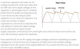
I’ve got new [power supply] capacitors (and a chicken stick to discharge the old ones) I can use [FOR THE POWER SUPPLY - edit] to see if this is where the 120 Hz is coming from. [amp is about 20 years old, it’s possible the caps are cooked - edit]

didn’t mean to confuse, just type faster than I think sometimes and got the order inverted somewhat.

Thanks, @gadget73
 
Last edited:
Back
Top Bottom