• The move to the new server is done. There are some software and database maintenance updates in process. This has us passing the hat around to help out. We appreciate any donations. Seriously, even a dollar helps. The payment page may be found here - https://www.audiokarma.org/support.html

500c Restoration Chronicle

sabrefencer

AK Subscriber
Subscriber
I joined AK in February 2018 when I unpacked from long term storage, a 500c purchased new by my parents in 1964. I knew very little about the inside of a receiver at the time I posted this: https://audiokarma.org/forums/index.php?threads/pulled-my-parents-500c-out-of-storage-today.808567/

Fast forward 4.5 years and I have done a ton of reading and have several tube restoration projects under my belt, all with the help of the good folks here at AK (search my posts if you are interested). I still have not restored Dad’s 500c, but I have restored a different one, for practice :). This post is about the restoration of the second unit which was acquired from eBay last July. It was complete except for output tubes and came with a few extra pre-amp and tuner tubes. It has a wood case, and suffice it to say I think I got a good deal in the mid three digits.

The unit had evidence of prior work, replaced coupling caps, and there were a few resistors that were definitely not the original rating. I did not try to power it up. This unit dates from 1966, s/n 71022x.

After reading as many AK Fisher Forum threads as I could over four years, I put my restoration plan together, gathered all my parts and dug in. The end result was very successful, and the receiver sounds and looks great. I couldn’t have done this without the wealth of knowledge on AK. Dad’s 500c is next in the restoration queue, and will follow the same plan as this one, perhaps with a few slight component changes.

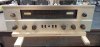
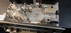
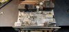
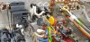
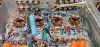
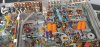
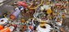
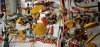
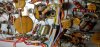
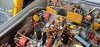
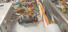
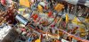
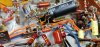
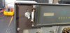
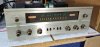
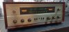
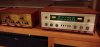
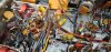
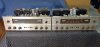
Unit on left is 1966 being restored in this thread, unit on right is 1964 (large # dial) purchased new by my parents. Remaining photos are of the '66 as received.

The restoration included what I consider the "usual" and necessary upgrades for safe and efficient operation, and several mods for performance, but I chose not to do some of the mods that have been discussed in this forum - no EFB (TM), no loudness, no RIAA, no reverb to pre/main in/out/ no tape monitor and a few others.

Details of restoration by section follow in multiple posts with lots of photos.

I'd love hear feed back from the regulars on this forum about what I did right, but more importantly what I can improve for the next one.

Thanks for looking (and replying) -- Gary
 

Attachments
  • 0315221636_HDR.jpg
    0315221636_HDR.jpg
    99.9 KB · Views: 93
  • 0724211453_HDR.jpg
    0724211453_HDR.jpg
    67.3 KB · Views: 85
  • 0724211453.jpg
    0724211453.jpg
    85.2 KB · Views: 90
  • 0724211453b.jpg
    0724211453b.jpg
    83.4 KB · Views: 93
Last edited:
Register to hide this ad
Power Input: New polarized (2 prong) power cord, 120v relay controlled by stock power switch, CL-80 thermistor in hot leg of power transformer, replace/upgrade CR5/CR7 with UF5408 diodes. Wired such that hot leg goes through fuse then to switch (relay) then CL-80 then primary. Neutral is unswitched. The power switch makes/breaks the neutral leg feeding the relay coil. The auxiliary outlets are unswitched and unfused. Replaced C103 with an X1/Y2 safety cap, and C102 with a poly cap.
 

Attachments

  • 0413221552d_HDR.jpg
    0413221552d_HDR.jpg
    103.3 KB · Views: 128
Power supply: Replaced three cans with Hayseed Hamfest. Replaced R133, R135, R137, R139 with 2W metal film. Replaced R136 and R144 with 5W wirewound, and R143 with 10W wirewound.
 

Attachments

  • 0407222229_HDR.jpg
    0407222229_HDR.jpg
    92.6 KB · Views: 114
  • 0408221730.jpg
    0408221730.jpg
    86.4 KB · Views: 114
  • 0408221731a_HDR.jpg
    0408221731a_HDR.jpg
    87.3 KB · Views: 119
  • 0408221726_HDR.jpg
    0408221726_HDR.jpg
    126.9 KB · Views: 122
  • 0613221950c_HDR.jpg
    0613221950c_HDR.jpg
    101.3 KB · Views: 120
Bias Supply: Replaced Se rectifier with a BR3 3A Si bridge. Added UF5408 diodes on – and + outputs from rectifier (parts supplied by Jim McShane) not sure if this was necessary and did not do an A/B comparison of voltage without these diodes. Replaced can cap 97A/B with discrete caps, R142 with 5W, and omitted R131, R132, and C86, due to installation of IBBA. Installed Dave G’s modification to provide more -V to IBBA to support output tubes that need more negative bias voltage. Caps, diodes and related tie points are via a multi lug T-strip installed on a grounded stud through an existing vent hole.
 

Attachments

  • 0413221552_HDR.jpg
    0413221552_HDR.jpg
    94 KB · Views: 118
  • 0613221949e_HDR.jpg
    0613221949e_HDR.jpg
    94.5 KB · Views: 116
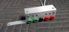
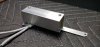
IBBA: Built IBBA board per Dave G’s 2014 sketch, and built an aluminum housing mounted on the rear of the receiver. IBBA installation includes running new bias feed wire to IBBA board, removal of existing bias wiring, installation of two 3 lug T-strips on heat shield studs to provide separate tie points for feeds from IBBA to grid return resistors (which remained at stock 330k value), and leads from IBBA test points to pin 5 of each output tube. Wiring from IBBA was via 24AWG cat5 internet cable which provides 4 pair -- one color coded pair for each tube. Ground and -25v feed were via 20AWG in a sheath from another length of cat5 cable.
 

Attachments

  • 0622222050a_HDR.jpg
    0622222050a_HDR.jpg
    79.9 KB · Views: 139
  • 0413222041_HDR.jpg
    0413222041_HDR.jpg
    91.6 KB · Views: 129
  • 0413222041a_HDR.jpg
    0413222041a_HDR.jpg
    99.4 KB · Views: 125
  • 0413222032b_HDR.jpg
    0413222032b_HDR.jpg
    119.7 KB · Views: 139
  • 0405221540c_HDR.jpg
    0405221540c_HDR.jpg
    59.1 KB · Views: 142
  • 0405221541_HDR.jpg
    0405221541_HDR.jpg
    62.9 KB · Views: 138
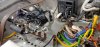
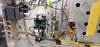
Output stage modifications: Replaced jumpers from pin 5 to ground with 10ohm 1/4W metal film (cathode) resistors, removed buss wire connecting adjacent tubes, installed screen stopper resistors between pins 1 and 4 (used 274 ohm 1/4W provided by Jim McShane) – may use 100ohm in next unit. Moved orange (B+ feed) from pin 8 to pin 1 of V8, and then daisy chained to pin 1 of remaining tubes. Connected R143 to pin 1 of V9.

Photos show output stage mods, coupling caps, separated 330k grid return resistors (light blue), cathode resistors (small darker blue) and work done on output tube sockets.
 

Attachments

  • 0418222115b_HDR.jpg
    0418222115b_HDR.jpg
    128.3 KB · Views: 128
  • 0419221355b_HDR.jpg
    0419221355b_HDR.jpg
    84.5 KB · Views: 117
  • 0419221346f_HDR.jpg
    0419221346f_HDR.jpg
    132.9 KB · Views: 116
Phase Inverter section: Installed “noose” removal bias correction modification with heater bias upgrade per Dave G’s design. This included relocating 220ohm bias resistors from bias cap area to left Phase Inverter (V12). Replaced coupling caps (C77-C80) with stock 0.47uF value 715 series orange drops, and replaced C69, C70 with 47uF 35v Nichicon UKW electrolytics.

Photos show both Phase Inverters with noose mod installed, and details of left and right PIs
 

Attachments

  • 0420221833_HDR.jpg
    0420221833_HDR.jpg
    135.8 KB · Views: 107
  • 0419221212c_HDR.jpg
    0419221212c_HDR.jpg
    96.3 KB · Views: 96
  • 0418222115_HDR.jpg
    0418222115_HDR.jpg
    110.5 KB · Views: 93
Tone section: Replaced ERO foil caps C52, C53 with .047 400v poly caps.
 

Attachments

  • 0613221949c_HDR.jpg
    0613221949c_HDR.jpg
    118.3 KB · Views: 86
Phono/Input stage: Implemented Tape Monitor to AUX bleed circuit mod (another Dave G innovation) by removing C30, and C32. Replaced caps C13, C14, C16, C17 in phono section with poly caps, may use PIO caps in next unit. Replaced vibration isolating rubber grommets for V16-V17 sockets.

First two photos show why grommets need to be replaced. Don't compress the new grommets when re-installing and use permanent lock-tite to keep hardware in place.
 

Attachments

  • 0330221608a_HDR.jpg
    0330221608a_HDR.jpg
    102.2 KB · Views: 88
  • 0330221801.jpg
    0330221801.jpg
    34.3 KB · Views: 78
  • 0330221614.jpg
    0330221614.jpg
    63.9 KB · Views: 78
  • 0330221614_HDR.jpg
    0330221614_HDR.jpg
    100.7 KB · Views: 77
  • 0330221819_HDR.jpg
    0330221819_HDR.jpg
    91.1 KB · Views: 80
FM/MPX sections: FM front end: Replace electrolytics C51, C85 with electrolytics, replaced C57, C210 with poly, replaced C59, C61, and C72 “mustard” caps with poly. Replaced R36 with 5W, and R37 with 2W. Replaced MPX section caps C208, C209, C 214, C215, C221, C222 with poly caps. Installed Dave’s mod to lower stereo indicator threshold by adding a 47k ohm 1/4W resistor in parallel with R204. Installed mod to change FM Mono de-emphasis. Replaced R98 with 2.7k and 39k in series. Resistors were selected and measured to provide 41680 ohms, resulting in RC timing/FM de-emphasis of 75.024uS. Did not change stereo de-emphasis. Installed Dave G. mod to provide reduced B+ voltage to MPX-65 sub chassis, by extending existing t-strip addding 22uF cap and 12k 2W resistor.

Photos show new caps in MPX-65, new R36/R37, Mod to reduce B+ voltage to MPX-65 and "mustard" cap replacements, series resistors for FM mono de-emphasis mod, and new 47k in parallel with R204.
 

Attachments

  • 0602221358b_HDR.jpg
    0602221358b_HDR.jpg
    114.1 KB · Views: 72
  • 0604221550a_HDR.jpg
    0604221550a_HDR.jpg
    59.4 KB · Views: 65
  • 0602221358_HDR.jpg
    0602221358_HDR.jpg
    129.6 KB · Views: 70
  • 0602221359d_HDR.jpg
    0602221359d_HDR.jpg
    105.2 KB · Views: 64
  • 0613221948e_HDR.jpg
    0613221948e_HDR.jpg
    130.8 KB · Views: 63
  • 0613221948f_HDR.jpg
    0613221948f_HDR.jpg
    109.1 KB · Views: 66
Last edited:
Finishing touches and FINAL Product:

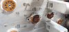
Installed a quad of vintage Westinghouse 7591s that tested OK, but certainly not new. 12AX7s in phono and pre-amp are all original Fisher labeled Telefunken that tested very well, with Sylvanias in the MPX section. The remaining tubes are a mix of Fisher/TF and USA made tubes. Thoroughly cleaned chassis, full Deoxit/fader lube treatment, replaced dial glass light blocking foam, and rubber edge molding on chassis front panel. Added informational labels regarding +70v DC on lighting, new PI adjustment procedure, and IBBA adjustment procedure. Polished knob rings and knob caps (these appear to be aftermarket replacements, but they are solid brass and polished up nicely). Rubbed the case with Howard’s and she was done.

Photos show old foam on dial glass and old rubber on edge of front chassis panel; new foam, new rubber edge, and new LED festoon lamps. Warning labels for DC voltage present on lamp sockets due to PI heater mod, and for new PI adjustment procedure. Photos of finished unit on bench and in listening room with little brother X101-ST, which I restored last year.
 

Attachments

  • 0329221444a_HDR.jpg
    0329221444a_HDR.jpg
    54.7 KB · Views: 82
  • 0614222050a.jpg
    0614222050a.jpg
    56.8 KB · Views: 77
  • 0622222051.jpg
    0622222051.jpg
    62.7 KB · Views: 78
  • 0617221854a.jpg
    0617221854a.jpg
    82.7 KB · Views: 70
  • 0622222125a_HDR.jpg
    0622222125a_HDR.jpg
    60.3 KB · Views: 71
  • 0624221322.jpg
    0624221322.jpg
    57.6 KB · Views: 75
  • 0614222053.jpg
    0614222053.jpg
    76.9 KB · Views: 73
  • 0614221503.jpg
    0614221503.jpg
    71.1 KB · Views: 78
Last edited:
Final results and questions:


1) Testing the completed unit, both channels began to clip on the scope at about 25 watts, which seems about right with tubes set on IBBA at 350mV which is just under 37mA current draw per tube, which is about 77% of max dissipation.

2) Measured distortion at 16ohms and 8ohms, where THD remained below 0.25% through about 6 watts, below .5% until about 10 watts, and increased to about 0.9% at 23watts, and about 1.0% before clipping set in at approximately 25 watts RMS. 500c distortion specs published in the operating manual p14 are: 0.7% at 1kHz at rated power of 33 watts RMS (one channel driven). So, accounting for limitations of my test gear (HP334A analyzer and Heathkit IG-72 generator), these measurements don’t seem too bad to me.

3) The only build questions I have relate to the orientation of certain caps. I learned that the cap lead connected to the outside foil should go to ground, or the lower potential side of the circuit. With this in mind, I installed the coupling caps with the outside foil side toward the PI plate (pin 1) and the other end to the grid resistors. BUT – Fisher seems to have put the originals in the other way – I have looked at several other units and they are consistent – outside foil line is toward the resistors. Same for the ERO Foils (C52, C53) which connect to the plates of V14 in the pre-amp. These were installed two different ways – C53 has the line toward the plate, and C52 is the other way. The only difference is that C52 is for the left channel, and C53 is right, so why orient the caps differently. Again, I installed both caps with the outside foil toward the plate (pin 6 and pin 1). Should I have followed Fisher’s method? What is Fisher’s method? If anyone can shed light on this, and provide the “correct” way to install these caps, that would be most helpful. I doubt I will change them in this unit, but before I do another one, it would be nice to know.

I look forward to your comments, and once again thanks to all who contribute to the ever expanding wealth of knowledge that is Audio Karma.
Gary
 

Attachments

  • 0315221609a.jpg
    0315221609a.jpg
    123.8 KB · Views: 58
Very nice restoration.

I've also had questions about the correct orientation of capacitors with regard to the outside foil side after viewing Paul Carlson's Youtube videos on the subject. My understanding, after hearing the responses of several individuals much more knowledgeable than me, was that the consensus was that the orientation of modern caps was not a concern due to their smaller size and less susceptibility to picking up external noise compared to older, much larger caps. That is why the manufacturers no longer bother marking the outside foil lead in most cases.

If someone knows otherwise, I would certainly like to hear.

Just one more point: Saw a video today where Mr. Carlson says that the capacitors are not marked because the manufacturers expect that the caps will be installed on a circuit board close to a ground plane and not point-to-point where they are more prone to pick up noise/cause oscillation if installed “incorrectly”.
 
Last edited:
I'm more curious about how you like the sound. I enjoyed your pictorial tour. I'm a 500-C tinkerer (too?). Without knowing how good it sounds I'd say NICE JOB ! You certainly seem well acquainted with the details so that puts you well ahead of the game. Enjoy your efforts and rock the room !
 
I always admire well thought out, meticulously and neatly implemented restorations. Yours fit that bill: Bravo!!

FWIW: I’ve never paid attention to foil orientation in caps other than the few I replaced in my CX2 pre. I always doubted my ears would be able to pick up any difference.
 
I'm more curious about how you like the sound. I enjoyed your pictorial tour. I'm a 500-C tinkerer (too?). Without knowing how good it sounds I'd say NICE JOB ! You certainly seem well acquainted with the details so that puts you well ahead of the game. Enjoy your efforts and rock the room !
Thorne
It sounds very good. I need to do more critical listening but my initial reaction is tha I am very happy with the sound.
I want to give you a shout out, for your photo of the underside of a stock 500c with components identified, which was a huge help in navigating under there. I also used your list of mods to help me decide what I was going to do it.
Rock on.
 
I always admire well thought out, meticulously and neatly implemented restorations. Yours fit that bill: Bravo!!

FWIW: I’ve never paid attention to foil orientation in caps other than the few I replaced in my CX2 pre. I always doubted my ears would be able to pick up any difference.
I agree that cap orientation is not as important with modern poly caps. But that still does not satisfy my curiosity as to why Fisher put the caps in the way they did when presumably it did matter.
 
sabrefencer - I'm very glad my PHOTOFACT helped you. I put a lot of work into my 500-C and I needed a PHOTOFACT. Since there wasn't any and since I spent so much time identifying the parts in mine, I thought it was a good idea. It's kind of messy which is why I created the grid-lines version which gets you to the area of interest faster, arcane as it is to figure out how to use it. :)
 
Back
Top Bottom