• The move to the new server is done. There are some software and database maintenance updates in process. This has us passing the hat around to help out. We appreciate any donations. Seriously, even a dollar helps. The payment page may be found here - https://www.audiokarma.org/support.html

500C Restoration Plan and Questions

sabrefencer

AK Subscriber
Subscriber
I first posted to AK in 2018 about a 500c my parents bought new, and I pulled from the box I had saved it in 12 years earlier. At the time I had little experience restoring vintage audio. I asked a bunch of noob questions which gave me direction and motivation. Four years later, I still have not restored the 500c, which is a ‘64, but have been learning, building my bench, and have done several other tube amp restorations, so I think I have the skills to do this right. Since 2018 I have also acquired a second 500c (1966) and an 800c Executive from 1964. Two years ago I bought a set of Hayseed Hamfest caps, and a “kit” for the remaining parts from Jim McShane. In a few cases, I don’t understand the rationale for the parts Jim included – they are all high quality parts, but some of them are different from recommendations I have seen discussed in the threads.

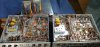
I spent the past week with the two 500c’s belly-up and side-by-side, looking and taking notes. The ’66 came from eBay with a few spare parts and after examination, I can see it has had some work done to it that is definitely not correct, it also has a few factory differences from the ‘64 (mostly in the FM section). The family heirloom ’64, in the photos on the right with the large number dial, looks like it has not been touched inside, except for me replacing a broken fuse holder and adding a CL-80 in 2018.
0315221636_HDR.jpg 0316221205_HDR.jpg

I have decided to work on the ’66 first and then replicate the effort on the ’64. The 800c will come later.

I have been reading about 500c’s on AK for four years, and been through the stickies and the various posts many times over, and I’m still finding new stuff. From reading these posts, and from posts related to my other projects, I feel like I know several of you very well.

Even with all the info, I have come across only one or two lists of what to do and how to do it to a 500c that are not complicated by the fog of variations for the 400 or early s/n 800c Executive - sorry Larry D, I couldn't resist. To that end, I have spent a good part of a week putting together my modification plan for the 500c, which reflects my goal to do most, but not all of mods that are possible. This plan is broken down by section of the receiver: power input, high voltage supply, bias supply (including individual bias adjustment), phase inverter, output stage, phono/input stage, tone control section, and FM/MPX. These are listed in the rough order I plan to do the work. I have also listed cosmetic, mechanical, and miscellaneous modifications. For each of these sections I have listed the changes or mods, major steps for more complicated changes, and the parts required.

See attached restoration plan below.

I have a few detailed questions, which are grouped by the sections of my plan. I will ask questions a few at a time to keep the discussion on topic. The question numbers are from the restoration plan. There are gaps in the number/letter sequence, because I only have questions on some topics.

Questions:

1 Power Input
1C – I intend to replace C102 and C103 black beauties. Jim McShane's kit provided .01uF 1.6kV polypropylene as replacements. C103, is on the primary side of the power transformer and looks like a “death cap.” C102 is on the secondary. Would an X1/Y2 rated disc cap be a better choice for either or both of these locations than the polypropylene caps?

1E – Jim’s kit included a pair of UF5408 fast diodes (rated at 1kv 3A) intended to replace CR5 and CR7. These seem adequate, but I don’t know the rating of the stock diodes. Please confirm that Is this an appropriate upgrade.


2 High Voltage Supply
2F – Jim’s kit provided a 1.2k ohm 5W resistor to replace R143. The specified stock value which is in my ’64 is 1.2k ohm 7W. My ’66 receiver has a 1k ohm 10 watt in it, that looks like it could be original. I would like to use a 1.2k ohm 10W, any reason not to?


3 Bias Supply
3B – Jim’s kit supplied two more UF5408 diodes to be added to the + and – DC outputs from the bridge rectifier before the bias caps (C97 A and B). He calls these “noise buffers”. I'm not exactly sure of their purpose, perhaps extra rectification. Are these a good idea to install in this location?


More questions to follow after a few responses to these questions have been received.

Thanks in advance,
Gary
 

Attachments

Last edited:
Register to hide this ad
All part #'s are Mouser #'s.

1.
) C-103 gets a X-Y cap. C-102 gets one of McShanes.

1E.) UF5408's are a bit of Overkill (1000V / 3A rating) where the originals are IIRC 400V 1.5A rated. 400x series is too small. If you've got the 5408's, go ahead and use them.

2.) Use the 10W. Ohmite makes a good one approx the same size as the 7W original. The circuit dissipates almost 5W which gives you about 128% overhead with the 7W. A 10W gives you 200% overhead in wattage and won't strain as much. It'll still get hot, but it won't be as hot. 1.2K 10W 5% 588-40J1K2E Ohmite 1.2K 10W 10% Ohmite.....588-20J1K2E. I've used both in various FISHERS. Actually the 5% is $.09 cheaper than the 10% resistor.

3.) The only thing I can think of why the extra diodes btwn the bridge and the bias caps is to lower the voltage a volt or 2. You're gonna replace the Selenium bridge rectifier with a silicone unit. No real need for the UF5408's. 8A 400V is a bit overkill, but it's inexpensive. 583-BR84 This is the one I use in all my FISHER's.
 
Larry,
1. C103 as X-Y confirms my thoughts re: "safety cap". C102 polypropylene makes sense, I assume since it is not a "death cap". I've got both, so I am good to go.
1E. I do indeed have the UF5408s so I will use them. This speaks to Jim using good parts.
2. I already had the 1.2K 10W 5% 588-40J1K2E Ohmite in my next order to be placed with Mouser. I also determined that it is just about the same length as the stock resistor, so should fit great. -- thanks for confirming.
3. I originally bought an 8A bridge (based on one of your much older posts). Jim supplied a 4A, and I have several of these in stock. I will likely go with the 4A unit. Regarding the extra diodes, I may start with them in place, but if my voltage readings get too low (also using CL-80), I will know that these diodes may be the culprit.
Thanks for response, in spite of me razzing you about early 800c Execs :beerchug:.

More questions to follow.

Gary
 
Next set of questions:

4 IBBA mod

4F. I am planning to use Cat5 internet cable which is 24AWG. 24AWG is rated for 3.5A and Cat5e is rated to 125v DC. If I am not mistaken, the leads between the board and the balance pots are carrying -22v DC in the milliamp range, and the test points presumably about the same, it seems the 3.5A cable should be fine. I am looking to confirm that this type of wire (cable) is appropriate.

4H – I am planning to locate the board and test points on the outside rear of the chassis (like many others). I am trying to determine the best place to tie in the ground from the board and the gnd test point. I am better off keeping the ground lead short and connecting to a ground point near the board, or is it better to run a lead and connect to a ground location near the output tubes, for example one of the tube socket ground lugs where the cathode resistors connect?

5 Output Stage Modifications


5A – Are metal film resistors a good choice for the cathode resistors (10 ohm ¼ watt)?


5D – I will be installing screen resistors. Most of the info on AK points to using 100 ohm ¼ or ½ watt. Jim’s kit supplied 274 ohm ½ watt precision metal film resistors, made by Vishay/Dale (Mouser 71-RN70D2740F.) Again, Jim's kit included quality parts, these resistors are more than a $1.50 each and I have them. But should I use these or the 100 ohm 1/4 watt, which I also have, and why?


5H – C82 and C84 are ceramic disc caps connecting the grid return resistors to ground. I have seen some discussion on these in the threads, as there appear to be some discrepancy as to the correct rating of these caps. The 500c schematic (30001-49999) shows these as 10pF, but has them as 18pf on the component list. Their value in both of my 500c units is 18pF. Jim’s kit supplied 20uF silver mica caps as replacements, but also provided 200k grid return resistor replacements along with .1uF coupling caps - which I will not be using since I plan to keep the coupling caps and grid return resistors at the stock values, since I am installing individual bias adjustment on the outputs. Not sure if Jim's substitution of 20pF for the original 18pF had anything do with the value of the grid resistors, but unless there is a good reason to change the value of these, I intend to replace the ceramics with 18pF silver mica caps. Is there any reason I should change the value to 20pF?

6 Phase Inverter -- I am planning to install the "noose" removal mod - no questions on that at this time. But just one clarification:
C69 and C70 are 50uF 10v electrolytic. Jim’s kit provided 100uF, 100v Nichicon muse radial caps as replacements. These are great caps, I just want to confirm there won’t be any issue with the additional capacitance.

Thanks,
Gary
 
Great questions, sabre. Great unit. I'm curious as to your choice for cabling the IBBA. Why ethernet cable as opposed to plain ol' 22 gauge? As for grounding, just don't create a new ground point. Use an existing one so you don't get into Ground Loop Hell. Also be careful with wire routing to your external IBBA board. Keep the wiring away from the power section especially if your grid return resistors are on the board and not inside the unit. I forget if there is signal passing thru IBBA, I don't believe so, but you want to keep stray EMF out of the wiring. Good luck ! Looking forward to reading your progress. My 500-C is has been my tinkering nirvana.
 
Thorne,

Thanks for the encouragement. By the way I have been relying heavily on your "Stock Marked" photos with component IDs and your mod list -- both very helpful tools. I may have a few new component IDs for the photo. When I finish the work, I will send you a note with my input. Regarding ethernet cable, it is small enough to fit in the vent holes, easy to route, and I have a ton of it. Good call on carefully routing this, as it is not shielded (at least not the stuff I have). However, I plan on leaving the GR resistors in their stock location. Regarding grounding, good call to not create a new ground point, but roughly where should I be looking for existing candidates? I'm thinking about running a ground lead from the board to the ground lug on the socket for V8 (most inboard of the output tubes).
This lug will will also be the ground point for the cathode resistor for that tube, I wonder if that will cause any issues with measurements.

Gary
 
Last edited:
Gary;

Cat5 should be ok. Like Thorne said, keep it away from the power supply and route the ground to an existing ground point. As for mounting it outside, I'm not the guy to ask, as I mount mine internally.

Metal film resistors (both the cathode and screen stab's) are a very good choice. They have a distinctive snap like "POP" if/when they blow. Use the 1/4W as they are also used as tube fusing, so if/when they do blow it shuts the tube off. As for value of the screens 100ohm is the minimum. Read this Article by Dave Gillespie on Maximiing Output tube life. He gives a range that is acceptable, and your 274Ω resistors are within the range. http://www.tronola.com/Gillespie2544.pdf

C69/C70. There's less than 3v on that part of the circuit. If you have a 47uf 16V or 25V, that would be max voltage I'd allow for the cap. a 100v cap in a 1.1v circuit don't make any sense, unless it's the only this you have and nobody has the lower voltage caps. Nichicon UKL's are fine here. No need for Muse caps. Save them for something else.

C82/C84. Fisher tended to use very good quality ceramic caps here. I tend to leave the original ceramics in except in 2 cases (1. the cap is open or 2. the cap is out of spec) The 10pf/18pf thing may have been an oversight on the drafter making the schematic. I just checked both my 800's. Both have the 18pf. So it's probably a drafting error. If it reads ok within 5% leave them in.
 
Gary,
Great looking receivers. I've got a very similar situation as you, except I've got a pair of 400's instead of your 500c's. I went the same route as you - Hayseed and McShane. Although on my second unit McShane stopped responding to me when I was placing the order so I had to go the Mouser route. I hope he's okay. I installed everything McShane sent to me except for the screen resistors (he sent 1K resistors and I put my own 100 ohm resistors in instead- per Dave Gillespie). Jim sent (3) UF5408's to me with (2) being replacements and extra one for bias. I installed all of them with no issues. Also, Jim sent a biasing pot that I installed in the first unit but I'm going the IBBA route on the second one (If I can get it figured out). Anyhow, the first one sounds unbelievably good and I'm about 90% complete on the second one with only the IBBA to go. Good luck on yours.
 
K Cat,
Jim provides good parts that will work, some of them are just slightly different from the parts that the AK Fisher community is dialed into. Since I ordered these parts from Jim, I have have done quite a few other restorations, for which I did the research and chose which parts to use - this is a time consuming process, and I did not always get it right the first time, Therefore, I would not hesitate to recommend Jim's kit to other restorers. I assume Jim is very busy dealing with a run on Russian tubes this past month, perhaps that is why you have not heard back from him.
Good luck with the 400s.
Gary
 
Last edited:
Larry thanks for the confirmation and input to post #8. I agree regarding C69/C70, I have some 47uF 35v UKWs in my stash, which should work fine, and they are much smaller physically than the 100uf 100v muse. Regarding the 18pF (C82/C84) the 20pF caps from Jim are 11% over spec, so not going to use them. The only way I have of measuring caps under 1uF is with my Fluke 117, which does not provide much precision, but if they don't read 18pF, I will replace with 18pF silver micas.
 
One other comment about Jim’s parts, the PIO coupling caps that he supplied are huge. They sound fantastic but I had to get creative to fit them in. C7C89804-3A72-492B-8259-A7D769148C0F.jpeg
 
Paper-in-Oil for coupling caps??? Interesting. I put them in the PHONO section. Are these between Pase Inverter and output stages?
 
One other comment about Jim’s parts, the PIO coupling caps that he supplied are huge. They sound fantastic but I had to get creative to fit them in. View attachment 2520426

K Cat,

Those are 0.1 caps (Russian K40y9). They are great caps. He also supplies 200k grid resistors. This has been the topic of much discussion in other threads. In summary, this combination is OK, especially if you don't have individual bias adjustment. But thinking has evolved. The go to combinations of coupling cap and grid resistor ratings are: 1) stock 330k with .047uF -- in conjunction with individual bias adjustment (IBAM or IBBA) for the 7591s, OR if you don't have individual bias adjustment, the first choice would be to lower the value of the grid resistors to 220k and use .068uF coupling caps. The reason has to do with the time constant of the RC (resistor/capacitor) network. The time constant of the 220k/.068uF is closer to stock than the 200k/0.1 combination. I have attached a thread that covers this, in particular, in post 15, I have attached the calculations for various combinations of resistors and caps. Bottom line, is you are probably fine with what you have, as the lower (200k) resistors take strain off the tubes, which is the reason for the change.

https://audiokarma.org/forums/index.php?threads/800-executive-arrived-today.963945/
 
Paper-in-Oil for coupling caps??? Interesting. I put them in the PHONO section. Are these between Pase Inverter and output stages?

Thorne,

PIOs as coupling caps is not new. Jim McShane supplies them, and I used them in my X-101-ST. I am going to use them in this 500c build. However I will be using the stock value of .047 and keeping the stock value of the grid resistors (330k). Dave G says this is perfectly fine, but only if the unit also has individual bias adjustment. If not, use .068 and 220k -- the lower resistor value to take strain off the tubes, and .068 cap value to keep the time constant close to stock (a delta of only -4%).

Gary
 
Thorne,

The caps in question are C77, C78, C79, and C80 (stock value = .047uF), and resistors R121, R122, R123, R124 (stock value = 330k). They are between the PI and output tubes.
 
I know the PI-output tubes caps well. I've tried 3 different combos to test the sound difference. Too hard to do A/B testing with components without some way to record high quality and then A/B-test the sound bites. I ended up with Sonicap v2 caps (cylindrical, white with black writing) only because someone recommended them as great audio caps. Frankly I can't say.
 
I've got K40's in my Executive 800c and yellow Illinois in my standalone 800c. I can't hear any difference. Other than those they are identically set up. Dealer's choice. I use Cornell dublier's DME types or Panasonic's in 90% of my gear now. Small, & easy to install.
 
Third set of questions, these are all related to FM/MPX:

9A I know it is good restoration practice to replace electrolytics in a unit of this age. There are also a few "mustard" color mylar, black mylar, and brown mica caps that seem like replacement candidates also. Are any of these caps typically replaced by other 500c restorers, and since they are in the FM/MPX curcuit will changing these caps have any impact on FM alignment, or cause other issues?
Specific caps are


Electrolytic:
C51 (2uF, 70v)..........replace with: 2.2uF, 100v electrolytic axial
C57 (.5uf, 350v).......replace with: .47uF 450v electrolytic axial
C85 (8uf, 50v)..........replace with: 10uF, 100v electrolytic axial
C210 (1uf, 350v) .....replace with: 1uF, 350v electrolytic axial

"Mustard" caps: C59, C61, C72, C107 (.1uF, 125v mylar) ....... replace with polypropylene, either: Nichicon .1uF 400v radial, or CDE/IC .1uF 250v axial

Brown (mica) caps: C208/C209 (4700pF 5% 500v), and C215 (3900pf 5% 500v)
Black (mylar) caps: C214 (4700pF, 400v), and C221/C222 (.047uF 250v)

These brown and black caps are not easy to get to, but if they need replacing, so be it.

9B -- Resistor replacement/upgrade:

R36 (4.7kW, 3W)......... replace with 4.7kW, 5W

R37 (3.3kW, 1W)........ replace with 3.3kW, 2W

9J -- When lowering the stereo indicator threshold, does the 47k resistor replace R204 (1M), or does it get added in parallel? My interpretation of what Dave G wrote: "For all units, the resistor is installed across R204, (i.e. from the anode of CR100 to ground)" is that the new 47k resistor gets added in parallel, and does not replace R204. Does the new resistor need to be 1/4W, or will 1/2W (lots of these in stock) be OK?

 
9J - Added in parallel. 1/4w or 1/2w is OK. Not much wattage is achieved so 1/4w should be fine. I'd follow the spec.
 
9A Replace all of the Lytics with Film, EXCEPT for C85 (8uf 50V) Use a 10uf 63V vs. a 100v lytic.
Replace the Brown and blacks. They have a tendency to go intermittent at the leads internally. Mustards are optional, but I replace them.

9B. Yep!

9J +1 with Thorne.
 
Back
Top Bottom