• The move to the new server is done. There are some software and database maintenance updates in process. This has us passing the hat around to help out. We appreciate any donations. Seriously, even a dollar helps. The payment page may be found here - https://www.audiokarma.org/support.html

500c Restoration - Power-up questions

sabrefencer

AK Subscriber
Subscriber
I’m restoring a 1966 500c. I obtained the unit from eBay about 6 months ago, and it showed signs of prior work, which included newish coupling caps, a few resistors that were not original spec, the power switch was replaced with a SPST, but it works. I made no attempt to power it up prior to working on it. I checked the transformers, and none were open or dead shorts, but I did not record the readings.

I did a bunch of work before attempting to power up, and on Initial power-up (using DBT and Variac) did not get any output. Initial measures of bias seemed “low”, about -18vDC across bridge, and mV readings at IBBA test points seemed high. I also got a small puff of smoke from the bias cap area, but I am hoping that came from heat shrink I used on the leads of R143 (5W 15 ohm), which served no purpose, and has been removed.

I’m looking for advice on power-up procedures, e.g. should all tubes be installed, or should some be left out until certain voltages are verified etc. Which voltages should I check first to make sure I’m not cooking anything etc. I did quickly check the high voltage DC feeds and these seemed OK, but did not do a methodical job, since was not getting output and not sure if something was wrong. (yes, I got a bit nervous)

Normally I would not do this much work to a unit before attempting to power on, but many of the items are related so I went ahead and did them.

I’ll post the work I did in the next post.
 
Register to hide this ad
Here is a list of the work that I did:


After a thorough cleaning and treating all pots, switches tube sockets and jacks, I went through the power supply, bias supply, output section, and Phase Inverter section and did the following work.

1. Installed new can caps from Hayseed Hamfest
a. 3 cans on top of chassis
b. Pair of discrete caps for bias underneath (see details in #3 below)
c. As part of the installation of new caps replaced/upgraded wattage of the following: R133, R135, R136, R137, R144, CR5, CR7, C102​

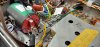
2. Updated AC line input as follows:
a. New polarized power cord wired as follows:
b. Hot leg goes through the fuse, then to CL-80 thermistor then to SPST relay controlled switch. Other pole of switch is to one leg of the PT primary. Hot leg also feeds one side of relay coil.
c. Neutral leg goes to other leg of PT primary, and also feeds the front panel switch. Other pole of switch feeds the other side of the relay coil. Closing front panel the switch engages the relay, which then connects the hot leg to the PT primary.
d. Replaced C103 with a Y2/X1 .01 safety capacitor
e. Installed a new 820k 1/2W resistor for R149.
f. Accessory outlets are wired directly from power cord (not switched, not fused)​

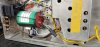
3. Revised bias circuit as follows:
a. Installed two 1000uF 50v Nichicon UHE 105c bias caps
b. Eliminated R131, R132 and C86
c. Wired bias to include D. Gillespie “more bias voltage” mod from 2019, which puts R142 (15ohm 5W) between the negative legs of the caps to provide -24vDC to heaters and -32vDC to IBBA board.
d. Replaced selenium rectifier with a BR3 3amp silicon bridge
e. Added Jim McShane provided UF5408 “noise buffer” diodes on both DC output legs of bridge rectifier ??? could this be causing an issue with the revised bias circuit?????

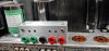
4. Built and installed IBBA board in home-built mounting housing (see photo)
a. Board is wired according to Dave G’s 2014 drawing
b. Points A/B/C/D (DC balance pots) wired to (now separated) grid return resistors
c. Installed new T-strips on heat shield studs, used to separate bias feed to grid return resistors
d. Removed old bias wiring, but did not remove factory T-strip near V11 (not connected to anything)
e. Test points wired to pin 5 of respective output tubes​

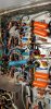
5. Revised output tube wiring:
a. Removed buss wire connecting tubes (pin 5 to pin 8)
b. Retained buss wire between pins 4 and 8 of each tube
c. Installed screen stopper resistors (274ohm 1/4 watt) between pins 1 & 4
d. Moved 375V B+ supply to pin 1 on V8, then connected to pin 1 in series on V9, V10, V11
e. Replaced R139 with 1.2k 2W, and moved to pin 1 of V10
f. Replaced R143 with 1.2k 10W, and moved to pin 1 of V9
g. Installed 10ohm ¼ watt cathode resistors between pin 5 and ground, removed jumpers​

6. Replaced coupling caps:
a. Kept stock value of .047uF
b. Replaced grid return resistors, keeping stock value of 330k ohms
7. Installed “Noose Removal” mod
a. Right Channel:
i. Removed R115 (180k) noose resistor
ii. Soldered 2-lug T-strip to heat shield
iii. Replaced R116 (68k) with 47k, connected to T-strip (non-grounded lug)
iv. Installed 91k resistor and 20uF 200v electrolytic cap between non-grounded lug and grounded lug on T-strip​
b. Left Channel:
i. Removed R113 (180k) noose resistor
ii. Soldered 3-lug T-strip to heat shield
iii. Replaced R114 (68k) with 47k, connected to T-strip (non-grounded lug 1)
iv. Installed 20uF 200v electrolytic cap between non-grounded lug 1 and grounded lug on T-strip
v. Installed 16k resistor between non-grounded lug 1 and non-grounded lug 2
vi. Installed 75k resistor and 1uf 350v electrolytic cap between non grounded lug 2 and grounded lug
vii. Removed R85 (220ohm) R120 (220ohm) from original location in heater bias circuit near bias cap
viii. Installed new 220ohm resistors from non-grounded lug 2 on T-strip to V12 pins 5 and 9 (heaters)​
c. Used “new” PI adjustment procedure to balance PI to value of 47k resistor,
i. Right = 47.01k ohms
ii. Left = 47.08k ohms​

8. Miscellaneous changes:
a. Replaced C69 and C70 with .47uF 35v radial electrolytics
b. Replaced C51 and C57 part of FM circuit, but located near other components being replaced.
c. Removed Aux/Tape Monitor bleed circuit. Per Dave G., removed C30/R33, C32/R34​

Before powering up:
1. Installed a set of used but tested tubes (not new production)
2. Set impedance selectors to 8ohm and connected speakers
3. Used a jumper to bypass AC relay to allow lower voltage to flow into unit
4. Connected an input to AUX and set selector switch to AUX input
5. Connected to DBT/Variac
See photos below, I have plenty more with detail, if there are questions about how something is connected.


Attachments

  • Bias and AC in.jpg
    Bias and AC in.jpg
    118.2 KB · Views: 47
  • Output and PI.jpg
    Output and PI.jpg
    135.8 KB · Views: 45
  • IBBA Installation.jpg
    IBBA Installation.jpg
    91.6 KB · Views: 44
Last edited:
After stepping away for a day or so, I powered it up again - with no output tubes. There is definitely a problem in the bias circuit. R142 (15ohm 5W) revealed itself as is the source of the magic smoke.
The bias section has the mod for "more bias voltage" and also Jim McShane provided UF5408 “noise buffer” diodes, and an IBBA board. I am going simplify to get a baseline. I will remove the diodes and the "more bias voltage" mod, returning the bias circuit to stock design, but will keep IBBA in place for now.
 
I returned the bias circuit back to stock. I used a new hayseed bias can cap, pulled out the IBBA board, and ran a single bias feed to all 4 grid resistors, and re-installed C86, R131 (hiding behind C86 in photo) and R132. Powered it up (still no output tubes) got about -18v going to bias, and had to stop, because R142 is still putting out smoke (I used another new 15ohm 5W).

Hypotheses:
1) I am wiring something wrong that is staying consistent when I change the circuit from "more bias voltage mod" back to stock (very possible)
2) I am making different mistakes in each scenario that are causing R142 to smoke (less likely)
3) There is something else that I touched that is causing the problem, either in the coupling caps, output mods, or noose removal (quite possible) -- see Post 2 for description of work done and photo.
4) There is something that was a pre-existing condition in the unit that I have not addressed with my updates and mods (potentially the bias secondary of the PT -- I kinda doubt this one, but listing for completeness)

Post 2 has photos of the bias circuit as I originally wired it with the "more bias voltage mod in place".
I have attached a photo of the bias circuit in stock configuration as it stands now - note: I threw this in quickly (flying leads all over the place, solder joints tacked for easy removal, etc) and hopefully will be removed to go back to my original more bias voltage config with discrete caps.
Also attached a photo of outputs with IBBA leads removed (taped off), and temp bias feed (white wire) to 330k grid resistors

This is the point where I need Larry or Dave to come to my rescue :bye:

Thanks,
Gary
 

Attachments

  • Temp Bias feed.jpg
    Temp Bias feed.jpg
    133.1 KB · Views: 25
  • Stock bias circuit.jpg
    Stock bias circuit.jpg
    94.6 KB · Views: 23
Looking at your “stock” bias connections, you have the white wire (neg) and the purple wire (pos) coming off the rectifier. I can’t make it out in the pic but it looks like they are connected to the same tab. Am I wrong?
 
Bad angle on that photo. Purple wire comes from pos on rectifier and goes to half moon tab on cap (pos), resistor is also connected between this point and chassis ground. The other pos (triangle) tab on the cap goes to ground. White wire is from neg on rectifier and goes to outer tab on can. Since all outer tabs are common neg on can, the white wire in the yellow jacket for heaters, and R132 also connect to another outer tab. R132 then feeds the bias to the output tubes.

I've attached a better photo.
 

Attachments

  • Bias cap wiring 2.jpg
    Bias cap wiring 2.jpg
    98.2 KB · Views: 17
I think I found the problem. I thought I spotted a nick in the insulation of the wire going to the heaters, so I checked with ohm meter and found .3ohm between heater feed and ground -- not good. I pulled the heater wire and readings between the neg and pos terminals on the bias caps went way up (which is good). I traced the heater feed back to the tubes, and noticed that connection point for pin4 on V17 was very close, perhaps touching the mounting screw for the tube socket. This is one of the ones with insulating grommets, which I had replaced, this was likely the cause of the short. I also pulled back the insulation on the heater feed (which on this unit is an uninsulated solid ground wire in a cable with the insulated heater feed wire) and cleaned up the leads, but there really was nothing obvious.

Re-connected the heater leads and the reading with no tubes is open, and with all small tubes in place is about 13 ohms. This is similar to another 500c I have on the bench, which reads 27 ohms with all small tubes, but close enough.

I powered it up and am reading -26vDC directly from the rectifier and to the heaters, and -20vDC after R132 to the bias feed. R142 is not smoking, in fact it is cool enough to touch (very carefully). Sometimes its the little things that get'cha.

I might as well put the output tubes in and see what she does, and check all voltages. If that works OK, I will re-connect the IBBA and do some more tests.
 
Last edited:
I'm very curious about what you find. I did the same "more bias voltage" and got magic smoke from the 15R resistor, too. I started from scratch with the IBBA and used the original -24v bias voltage design but as I increased the voltage with a variac, I notice that the 15R resistor was getting warm right away. It took weeks to find a direct short in my -24v wire from the bridge to the IBBA.
 
Sorry, bunch of other things kept me from getting back to this project.
After running the receiver with the stock bias circuit (using a new hayseed dual cap) feeding the IBBA board, everything checked out and bias ran fine. Finally today a put the bias voltage mod parts back in (with a new 15ohm 5W resistor and it works fine. The resistor quit smoking and while it does get warm it is not hot. This increased the -DC voltage to the bias (IBBA board) from about -24 to about -26.4. This appears to be be a good thing, since before the mod, the bias pot was maxed out to get about 34mA, now 36mA is in the middle of the range.
 
Back
Top Bottom