
• The move to the new server is done. There are some software and database maintenance updates in process. This has us passing the hat around to help out. We appreciate any donations. Seriously, even a dollar helps. The payment page may be found here - https://www.audiokarma.org/support.html

6EU7 filament pins

62vauxhall

Addicted Member
After ignoring it for about six years, I decided to try again, assessing why the Heathkit AA-32 integrated amplifier I built in 1968 then re-built in 2013 has a lot of hum on the MAG Phono input. All other inputs are quiet so my assumption has been that the hum is originating in the area concerning V1 which is the MAG Phono pre-amplifier.
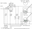
Heathkit AA32 schematic concerning V1.PNG

My initial attemps to find and eliminate said hum included rewiring it a 2nd time, installing 4 different 6EU7 tubes, reverting to the original capacitors connected to V1 and installing a tube shroud. Nothing helped. A vintage tube radio tech had a go at it and he couldn't diagnose the problem either.

All capacitors, resistors, tube sockets, power cord and switch plus the null hum pot are brand new as of 2013. The transformers, control pots and input selector are original. As mentioned, the amplifier works well with all inputs save for MAG Phono.

Last year I came into possesion of a variable DC power supply. To satisfy my curiosity I would like to disconnect V1 from it's 6.3 volt AC source and power the filaments from the DC power supply to see if that eliminates the hum. My question then concerns the 6EU7 in the V1 - phono pre-amp position.

I understand that the fillament pins are pin 1 and pin 2. Does polarity matter?
 
Register to hide this ad
I would love to see the assembly manual for this model, and some photographs of the power supply and phono pre-amp sections.

The most typical source of hum in an amplifier is not generally the filament string- because it is an indirectly heated cathode, although noise here =can= show up because of the parasitic diode that exists inside of the 6EU7/12AX7 triodes- The heated filament acts as a tiny cathode, and the actual cathode tube can act as a plate because it is at a higher voltage than the filament, so AC current can actually communicate from the heater wire directly into the cathode. The best cure for that is (as mentioned) to elevate the filament string so it is no longer below the actual cathode voltage. The most common way to do this would be to change the connection on the center pin of the hum pot- instead of connecting that to ground, connect it to one of the output tube cathodes, which runs a safe positive voltage.

Usually noise is coupled into a sensitive amplifier stage because high noise AC currents are allowed to flow through the chassis, and cause an AC voltage drop across the chassis, and this can couple a small AC voltage between the grid and the cathode of the phono amp triode. I would expect that Heathkit accounted for this in the assembly instructions- carefully indicating where particular ground should (and should not be) connected together. This is not shown in the schematic because it just shows everything ground as all one connection with no indication of where or how the connections are being made. Revisit the assembly instructions and make sure you did not play fast and loose with the grounds- that they connect only where indicated, and there are no other "extra" ground connections between ground domains, or grounds connected to the wrong place.

Generally, check these rules- There is a very high amplitude AC noise current that flows through the connection between the rectifier and the bypass capacitors- particularly, the connection where C100 and D2 connect to the negative side of the bypass caps- that should be a very short connection, and that system should connect to the chassis in only one place, usually referred to as the "star center" of a star ground system. Make sure that the grid return resistor (R1) and the cathode resistor (R15) of the phono amp triode (and the shield of that input cable, and the ground connection of the MAG RCA input) are tied together at the same point, so there is no voltage differential between them. Is the MAG RCA input grounded to the chassis at the connector?
 
Have you tried disconnecting the hum pot wiper from chassis and connecting it to the cathodes of the power tubes?

No, I have not. I've been tidying up the spot where I can get inside this amp again which is no simple task. I'll be done in a day or so, then there'll be room to open this amp up again. The suggestion re the hum pot wiper sounds like it should be easy to try.

The power tubes are 6GW8 and there are 4 of them. A copy & past from Google AI says the cathode pins for a 6GW8 are Pin 2: Triode Cathode and Pin 7: Pentode Cathode, Grid No. 3 (Suppressor), and Internal Shield.
 
I would love to see the assembly manual for this model, and some photographs of the power supply and phono pre-amp sections.

The most typical source of hum in an amplifier is not generally the filament string- because it is an indirectly heated cathode, although noise here =can= show up because of the parasitic diode that exists inside of the 6EU7/12AX7 triodes- The heated filament acts as a tiny cathode, and the actual cathode tube can act as a plate because it is at a higher voltage than the filament, so AC current can actually communicate from the heater wire directly into the cathode. The best cure for that is (as mentioned) to elevate the filament string so it is no longer below the actual cathode voltage. The most common way to do this would be to change the connection on the center pin of the hum pot- instead of connecting that to ground, connect it to one of the output tube cathodes, which runs a safe positive voltage.

Usually noise is coupled into a sensitive amplifier stage because high noise AC currents are allowed to flow through the chassis, and cause an AC voltage drop across the chassis, and this can couple a small AC voltage between the grid and the cathode of the phono amp triode. I would expect that Heathkit accounted for this in the assembly instructions- carefully indicating where particular ground should (and should not be) connected together. This is not shown in the schematic because it just shows everything ground as all one connection with no indication of where or how the connections are being made. Revisit the assembly instructions and make sure you did not play fast and loose with the grounds- that they connect only where indicated, and there are no other "extra" ground connections between ground domains, or grounds connected to the wrong place.

Generally, check these rules- There is a very high amplitude AC noise current that flows through the connection between the rectifier and the bypass capacitors- particularly, the connection where C100 and D2 connect to the negative side of the bypass caps- that should be a very short connection, and that system should connect to the chassis in only one place, usually referred to as the "star center" of a star ground system. Make sure that the grid return resistor (R1) and the cathode resistor (R15) of the phono amp triode (and the shield of that input cable, and the ground connection of the MAG RCA input) are tied together at the same point, so there is no voltage differential between them. Is the MAG RCA input grounded to the chassis at the connector?

As mentioned in my previous post, it will be a day or two before I can examine the underside of the chassis to compare the components with the points you cite.

Being as I had the assembly manual, I believe I followed the directions exactly as I had in 1968. After which, the amplifier performed properly for years.

But there are two possible proceedures that may have a bearing. One, is that I twisted the AC filament leads more tightly together than what was depicted in the manual and two, is that I scrapped the original lengths of shielded conductor and replaced it with new shielded conductor. The new shielded conductor is overall significantly thinner than the original was. I had used that thin shielded conductor before to make interconnects with no issues that I could detect. I therefore thought it would be suitable for use within this AA-32.

I have jpeg files stored on my computer, of the manual's assembly portion which are pages 9 through 31. Once I make the space to do the chore, I can post photos of the chassis underside.
 
I've been tidying up the spot where I can get inside this amp again which is no simple task. I'll be done in a day or so
Glad I'm not the only one that happens to. Kind of like playing one of those little sliding block games.

So the hum was not there when the amp was first built in 1968, then the hum problem showed up after you rewired later? Kind of narrows it down some.

You will want to connect the center wiper of the hum pot to the positive side of either C43 or C44, whichever is closer. Either will be around +7V, which is great. The amount of twist in the filament string does not matter, as long as you connected it correctly. The type of the shielded conductor does not really matter- only that you connected it as the assembly manual shows- if it wants only one side grounded, or if it wants both ends of the shield grounded, and where, etc.
 
You will want to connect the center wiper of the hum pot to the positive side of either C43 or C44, whichever is closer

I just tried this suggestion. Assuming I was to disconnect the wiper from it's attachment point, I did so then clipped one end of a jumper to the wiper tab and clipped the other jumper end to C44 +.

To my disappointment, the hum was worse. Plus there was a background noise of varying frequency that reminded me of trying to tune in a station on a short wave radio. As the volume control was increased, the frequency of that background sound rose higher.
 
@gadget73: "is the hum pot actually any good? I've had problems with those going open to one end and it causes all sorts of goofiness".


I've got the wire to the wiper disconnected but not the other two. I did a 2nd re-wire and it was a real hassle doing a re & re on that pot. I'll see what sort of readings I get on a DMM. That pot was a new one installed by the tech who tried learning what was causing the hum. The 2nd re-wire was done after the amp was returned.

The DMM was inconclusive. I would need to unsolder the wires going to the outside tabs of that pot. End to end I was getting rediculously low readings but at the wiper, they were more believable and did vary as I adjusted the pot.

I would need to disconnect that pot completely to assess it and it is a real pain in the a** to get at.
 
Last edited:
Back
Top Bottom