• The move to the new server is done. There are some software and database maintenance updates in process. This has us passing the hat around to help out. We appreciate any donations. Seriously, even a dollar helps. The payment page may be found here - https://www.audiokarma.org/support.html

6v6 (6p6s) se

PabloL

Active Member
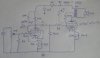
So I'm in the planning stage of a console type project, mainly a SE and PP amp in one unit to biamp speakers. PP for the woofer and SE for the treble. So I posted the PP schematic earlier and plan on building it as its posted, versus the changes I thought about making. But now its time to get some feedback on the SE amp. So the PP uses a Pentode gain stage and I thought I'd do the same for the SE amp. So I found a EL84 amp and subbed in the 6V6, since I've heard in various places that schematics with the EL84 can be used for 6V6's. Gain stage is a pentode EF86 or maybe a 6SJ7 and the power stage is a Russian 6V6 or the 6P6S. In my schematic I drew a few options.

Input stage. The schematic listed a EF86 in triode mode, but I have a bunch of 6SJ7's. So If I used those should I still use triode mode or should I use pentode mode. I read about pentode modes and drew some possible changes in dotted lines.

Output stage. This is a simple choice, UL, or Pentode. I really don't want to make a regulated screen supply. Many schematic have the screen supply coming off of the B+ through a resistor, or through another RC section, both of which would be ok with me. The other option is UL, but I've heard many conflicting views concerning 6V6's in UL. UL would be the easiest and the edcor opt has UL taps. Triode is another option but I'm not sure if I'd get the power I need. I'm hoping to get at least 4 watts.

Anyhow, please give me some input, guidance, advice, feedback, whatever. (no flames though! :) )
 

Attachments

  • DSCN0629.JPG
    DSCN0629.JPG
    110.4 KB · Views: 95
Register to hide this ad
The 6V6 will need a higher cathode resistor than an EL84 - maybe 360-390 Ohms, depending on supply voltage. The 6SJ7 should have a cathode resistor of about 7-8K for a 100K load - maybe 4.7K in pentode mode. With the output stage in pentode or ultralinear mode, you may want some local or global feedback to lower the output impedance (this will depend on your speakers - many need a low drive impedance for flat response). If so, use pentode mode for the voltage amp stage to have enough gain. But try it in triode mode first - it's simplest, and may give you what you want.
 
What Tom said..

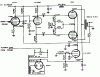
I modded your schem, and added local feedback (try it with or without).

I'd go UL with the Edcor tranny, I'd use 4.7k cathode on the driver to start for either
pentode or triode on that driver (should be in the ballpark) and a 390 cathode on 6V6.
 

Attachments

  • ef86_6v6.JPG
    ef86_6v6.JPG
    54.9 KB · Views: 79
Thanks guys

For the assistance. I figured since I was possibly changing both tubes in the schematic that some of the resistor values would change. I like the feedback ideas as well. I'm thinking that I'm going to power some small Co-axials with this for my shop amp. Maybe the Beyma 8XC20 or Radian 5208C.

So maybe 6SJ7 in pentode with some local feedback? I have a 75k trim pot I could use with a lower resistor to dial in my feedback.

Second question, the cap between G2 and the cathode, in the pentode driver stage. I read on the Valve Wizard site about how to calculate it but was lost in the math (I'm a History Grad Student for gods sake). But basically is was like the cathode bypass where the value effected the (low?) frequency roll off. I'm going to look at it again but if anybody cares to walk me through it, that would be very cool.
 
The capacitor should be a low impedance at the lowest frequency of interest, compared to the screen resistor. 1 uF is about 4K impedance at 40 hz, quite low compared to 330K. Z= 1/(2*pi*F).
 
The capacitor should be a low impedance at the lowest frequency of interest, compared to the screen resistor. 1 uF is about 4K impedance at 40 hz, quite low compared to 330K. Z= 1/(2*pi*F).

Well that would be ok because the small GX Edcor opts are only rated to 40hz anyway.
 
Interesting

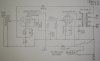
Have a look at this, basically what I'm trying to do. What do we think of this?
 

Attachments

  • R0019386-M.jpg
    R0019386-M.jpg
    40.1 KB · Views: 54
Last edited:
Yah that would be simular, but the output is running pentode, which is why there
running the loop feedback from the output tranny back to the driver, running in UL
I'd much prefer the local feedback Tom mentioned an I drew on the previous schem.

But having posted that schem made me look closer at the 6SJ7, in doing so I'd use
in the area of 1.2k for cathode resistor, those higher values will get you low current.
(I'd build with 1.2k then check your voltage on the cathode resistor to see the ma)

I think we are on the same page!
 
Back
Top Bottom