• The move to the new server is done. There are some software and database maintenance updates in process. This has us passing the hat around to help out. We appreciate any donations. Seriously, even a dollar helps. The payment page may be found here - https://www.audiokarma.org/support.html

6V6, Newcomb D-12, Bias Voltages

ttbccw

Active Member
Here is an interesting question:
A little while ago I restored a Newcomb D-12 amp. It sounds good, performs well...however...I've been using it on and off in a dedicated Mono 78/45 setup and I noticed the power transformer will get hot after about an hour of listening. I'm guessing the 6V6's are biased a little high. Here's why.
After 1 hour the power transformer gets pretty hot.
Incoming line voltage is 117acv to 120acv
The measured plate voltage is 344v, and according the schematic it should be more like 325v-330v
If I look at the tube data sheet for PP 6V6 it says max plate voltage of 285v.
I measured the resistance between pin 3 of the 6V6 & pin 8 of the 5Y3, the voltage drop, then plate current.
Plate dissipation is about 15.5watts...a little high. (344v vs 330v = 4.2% high.)
Should I change the bias on these? Both the SAM's and the scematic on the bottom of the unit have 325-330v on the plates...it just seems high? No?
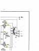
doc02305020190116123128_002.jpg doc02305020190116123128_001.jpg doc02305020190116123128_002.jpg doc02305020190116123128_001.jpg
 
Register to hide this ad
knock down the primary voltage until you get the heaters at 6.3vac. See if the rest of it measures right at that point. Fair bet the transformer will run cooler and it will bias closer to spec.
 
The voltage drop across the tube according to the schematic is 305V, with a current of 40mA per tube (20V across a 250 ohm resistor is 80mA). 305V at 40mA current equals 12.2W dissipation. In your case you'll want to check the cathode voltage to determine current, and yes your problem is a common one with today's higher line voltages.
 
Looks like that is self biasing. Power transformers are designed to get a certain temperature and a lot of times, they do get hot but it shouldn't keep getting hotter and hotter or you would see smoke and that would definitely indicate a short somewhere.

If you say it has been rebuilt, did you replace the main filter capacitors? One that is on its last leg would almost act like a short and bog down the power transformer.
 
I thought of using the variac to lower the incoming line voltage when I use it, but I figured that would be temporary. I would need a more permanent fix if the bias is in fact too high? Otherwise I have to use the Variac all the time. I will certainly use it to test the heater voltages like you suggest. I think the heater voltage was 6.7 when I tested them after the restoration. I don't remember for sure, and will test it again and see if lower incoming voltage brings everything back in line. They could be 6.3...
Higher line voltages now a days does seem more common. I don't know if anyone has a solution for this other than using higher dropping resistors (problematic in some cases), changing the bias network or just use a Variac. I did use a CL-80 thermister, but that only lowers the incoming voltage a couple volts-isn't going to cut it.
I did measure .045A (45mA) so that makes sense...a little higher than 40mA. I just wasn't sure the voltages on the schematics were correct either as it's PP 6V6's and the tube sheet has such lower max plate volts.

6V6 1: 258.5ohms across one side of the output transformer, 11.82 voltage drop across the resistor, .045A current, 344 plate voltage = 15.73w
6V6 2: 277.4ohms across the other side of the output transformer, 12.38 voltage drop across the resistor, .0446A current, 344 plate voltage = 15.37w

And because I did this almost a year ago, I don't remember much about the tests, but I have my summary sheet with my numbers on it. Maybe it did it wrong? I'll verify.
I replaced almost all the components in the amp. It was in pretty tough shape. All the tubes are the ones that came with it. I don't have a tube tester (yet) and I don't know how they test. The pots are the same, the transformers are the same, and the cathode bypass resistor is the same. I replaced everything else. The 250ohm 5w ceramic resistor tested perfectly. All the other carbon comps...not so much :)
This must have been stored in a damp garage for years or something. The power transformer is cool for like the first 20 mins. Then it gets a little hotter...and then after another 20 mins is hot to the touch, but not so hot that you can't put your finger on it....then at like 60mins its hot that you can't really touch it for long. I haven't used the amp any longer than 1-1.5 hours at a time.
Would a weak 5Y3GT effect this at all?
When I test the cathode, just from pin 8 to ground? Same as across the 250ohm resistor? Right? Right.
The plate voltage, for the 305v, is the voltage 6V6GT pin3 to ground, then 6V6GT pin 8 to ground, then subtract the cathode from the plate? That gives me the voltage to use in the equation? Then maybe I have the 344v wrong.
 
a bucking transformer is a nice way to do that. 124v at the wall is 6% over the old 117v standard, and thats exactly the difference in heater voltage. B+ will be 6% high as well.

Voltage across the tube is less cathode voltage, so if you measure 344 to the plate and 12v at the cathode, its actually 332v effectively.

The current at the cathode resistor is also plate+screen current, so using that current will be plate+screen dissipation. Generally we ignore that since the screen is a few ma, and getting plate+screen dissipation within the tube's plate dissipation gives a bit of cushion.

Weak 5y3 would usually just make for lower than normal plate voltage, and it would sag more under load. It wouldn't increase voltage or heat.
 
Yes you need to subtract the cathode voltage from the anode voltage in a self-bias circuit to find the voltage drop, but it's not clear how you got individual voltage measurements for the output tubes when the cathodes are tied together, there's only one voltage drop across the bias resistor. Perhaps that's with one tube removed in each case? If that's the case the voltage drop will probably be 24V with both tubes inserted (two tubes drawing twice the current), in line with the elevated plate voltage and resulting in lower dissipation calculation. It may still be slightly higher than design spec but probably not by a large amount.
 
I'm not sure if it would have any effect on the temp but I would definitely replace the cathode bypass cap. Those small lytics are almost always way out of spec, if not dead.

The voltage isn't extremely high, though. I'd be tempted to just change the bias resistor too and shoot for a plate dissipation of 10.5 to 11w.
 
Ok, upon further review and testing I realized...I must have done it wrong. The tests I did when I first completed the restoration are the numbers I was referencing. I tested the amp again last night and got different readings. I think I just need a little help with the plate dissipation math. Chances are good that I may be barking up the wrong tree with the cause on the hot transformer. And I think this might be a good example for toxcrusadr when it comes to changes in line voltage...at least with this amp anyway. And I COMPLETELY forgot about bucking transformers! And there aren't any original caps in the amp. Not one. Even in the tone section...& I didn't put that part of the schematic up.
And yes Selmerdave, I have no idea how I got 2 resistor voltages either....like I said I think I did it all wrong a year ago. ALL the voltages I measured before were much higher than what I got last night.

SO, I used my Variac to give me 117acv in. The amps says right on top "117vac" is what it expects. My actual from the plug voltage is more like 120vac. I tested the Variac output to be exactly 117vac with my multimeter.
These were the voltages with that AC voltage:
6V6 1:
Pin 3 to Ground 328vdc
Pin 4 to ground 333vdc
6.15vac for the heaters
21.68vdc across the bias resistor (which still measures 248.9ohms)

6V6 2:
Pin 3 to ground 328vdc
Pin 4 to ground 333vdc
6.15vac for the heaters
21.68vdc across the bias resistor

Then I put my meter across the "Hum Control" (Variable resistor across the filament supply, shunts voltage to ground) and increased the voltage from the Variac to get 6.3vac across the pot. Turns out the Variac was supplying 120vac for that. I got these voltages with 120vac in. (The pot is also one of the few original components)
6V6 1:
Pin 3 to Ground 335vdc
6.3vac for the heaters
22.26vdc across the resistor.

6V6 2:
Pin 3 to Ground 335vdc
Heater and resistor the same as above.

The 2 schematics plate voltages listed between 325-330vdc. My new measurements are much more in line with that. Actually I'm surprised just how good the new numbers are, not what I expected. But now to get the plate dissipation.
I'll use the 120vac supply numbers:
335vdc - 22.26vdc = 312.74 (313vdc)
313vdc/248.9ohms = 1.258? AND That's as far as I can get here....I don't know the math....BUT I think it will come out closer to what it should be than what I thought it was.

Maybe it's the bass response? It's VERY good...the new caps have given the amp a nice low end...maybe too much. Like all the way up on the bass knob gives me distortion (not that I use it that way)...That might stress the transformer/5Y3...and it may not be weak...might be the caps are too small for the increased bass response? I don't know...but the new measurements have me doubting what I thought it was.
And thank you all for the input, MUCH appreciated!
 
But now to get the plate dissipation. I'll use the 120vac supply numbers:
335vdc - 22.26vdc = 312.74 (313vdc)
313vdc/248.9ohms = 1.258? AND That's as far as I can get here....I don't know the math....BUT I think it will come out closer to what it should be than what I thought it was.

Maybe it's the bass response? It's VERY good...the new caps have given the amp a nice low end...maybe too much. Like all the way up on the bass knob gives me distortion (not that I use it that way)...That might stress the transformer/5Y3...and it may not be weak...might be the caps are too small for the increased bass response? I don't know...but the new measurements have me doubting what I thought it was.
And thank you all for the input, MUCH appreciated!

To measure the plate dissipation you start with the current measured across the cathode resistor using Ohm's Law.

I (current) = V (voltage drop) / R (resistor value)
I = 22.26 / 248.9 = .0894 Amps or 89.4mA

Dissipation = Plate voltage (measured between plate and cathode) x current
So Dissipation = 313v x .0894 = 27.98 (that's for two tubes)
27.98 / 2 = 13.99w per tube. Technically, that includes screen dissipation, but it's not much so it's usually ignored.

That's a bit high. Again, I'd change (increase) the value of the cathode resistor to get dissipation down to around 10.5 to 11w each so you're not running the output tubes so hard.

As for your bass response, I'd suggest turning the Bass control to its minimum setting and then slowly turning it up until it sounds good to you. Forget about any preconceived notions about what position it "should" be in. If it's not distorting at the point where you are satisfied with the level of bass, you have no problem.
 
drift in values in the tone controls will make the controls respond differently. Short of doing a frequency response test and finding the points where its basically flat response and marking that as the "center" position on the pot, just adjust by ear until it sounds best.

I wouldn't worry about it stressing the transformer though.
 
I did another test last night with the temp on the transformer...and I'm at a loss. It's fine. Yup. Temp measured with one of the laser pointer thermometers gave me 90F 20 mins in, 105F after 40, and after 70 mins it was only 120F. I swear it was hotter than that before I put it back on the bench! It felt cooler to the touch too. I don't know why. Like a car that doesn't make the noise when you bring it to the garage!
Yes, the pots have drifted, and I assumed that would be cause for some of the EQ issues. Also this amp has a very expansive EQ network. That's one reason I choose to buy it. It was a bay purchase. The seller noted that the can cap was getting too hot to touch and that's why I did the complete restoration. I do adjust by ear, and it does have great command over the EQ curves. I don't have an oscilloscope or signal generator...I'm kinda still building my bench up as funds allow.
SO if I do the equation with the 117vac:
I = 21.68/248.9 = .087A (87mA)
Dissipation = 306v x .087 = 26.62 (for 2 tubes)
26.62/2 = 13.31w per tube
If I use the voltages on the scematic:
I = 20/250 = .08A (80mA)
Dissipation = 305v x .08 = 24.40 (for 2 tubes)
24.4/2 = 12.2w
That's 1w difference. It is amazing how much the actual line voltage matters here. 2-3vac is all it takes.
I really appreciate the help on making sure I understand this better. I made some assumptions that were very wrong and I appreciate the help!
Looks to me like a bucking transformer will help. I can't explain why the transformer stopped being so hot, but I'll keep an eye on it as I use it. The actual voltages in the amp match better than I thought. Is it possible that they designed it to run 13w per 6V6GT? If so, it's back to spec.
 

Attachments

The Human hand is not a reliable indicator for subtle temperature changes. You can't tell 120*F from 150*F other than "IT's Hotter". @120*F you run the risk of scalding,and @ 150 2nd* burns (blistering). Which is one of the reasons that Water Heaters have been factory set to a MAX of 120*F. A Dishwasher will boost that 120*F to 150*F to 160*F for Sanitizing.

Transformers DO make a fair amount of heat, depending on Loads and input voltage,anywhere from room temp to 165 is generally acepted as OK. Above that up to 180*F is getting into dangerous territory . 190*F and above to be avoided at all costs as the transformer will usually melt down and go into Chernobyl Mode after a short period. The cooler you can get the transformers to operate under normal loads the better.

150*F to 160*F is NOT uncommon for some amps or receivers. Uprating or upgrading circuits to lessen loads while increasing performance (less distortion at the same time) can LOWER Transformer Temps. Case in point....I have a Sansui 1000A receiver that in stock form, using Sansui's mode of adjustments ran the tubes @ 110% of Max dissipation, and the Transformers were near meltdown @ bout 170*F. After overhaul, and upgrading it to a 4 bias pot circuit, and installing higher wattage heatsinkable power resistors in other locations away from the POWER Transformer, the transformers run @ a VERY COOL 120*F for the PT and 110-115*F for the OPTS. Tube selection played a large part in this. EH7591 (large bottle) tended to raise the temps about 10 * over small bottle Westie's or Tung-Sol 7591 Re-Issues.
 
This was a good thing for me to learn. Step by step. This Newcomb was the first real tube amp I restored. I did a 1934 Zenith and a small Webcor suitcase player. They were not the same as the Newcomb. I looked at a schematic for the Sansui 1000A. I see the cathode is connected to ground. I am guessing the modified circuit goes there. I didn't understand how the preamp tubes in the Newcomb were biased at first because they are tied to ground as well. I have only just begun to understand this. How the transformer plays a part, the current and dissipation...it's starting to make sense. And yes, hands are not real thermometers. :)
 
Back
Top Bottom