


You are using an out of date browser. It may not display this or other websites correctly.
You should upgrade or use an alternative browser.
You should upgrade or use an alternative browser.
6v6 PP choosing between 9k and 12.8k tran
- Thread starter Schmidlapper
- Start date


I assume your output transformer CT tap comes off of the positive lead of C2? If so, then use PSUD to get a feel for the resonant nature of your power supply. You can do this by adding a current sink in place of the final resistor on the right. Then step the current to double of initial current after say 5 seconds. This will give you a feel for how the power supply rings when responding to transients. It's highly dependent on the ESR of the caps and the DCR of the secondary winding though, so try to model those parameters as accurately as you can. Just eyeballing it, I would probably make C2 larger (maybe 220 uF) or L1 smaller (say 1.5H). Either of those mods will dampen the transient ring a good amount.
If the above ideas aren't feasible in your design, another tweak you can experiment with is adding a small value high wattage wire wound resistor in series between the output of the diodes and the first filter cap. Something between 2 and 5 ohms/5 watts. This can also tame the transient ring quite a bit. Just note if adding that resistor, it sees both AC and DC voltage drop (with the cumulative effects of heat dissipation as well), so the effects of voltage drop can be pronounced if the resistor is large. PSUD models this quite well though, so you will get an accurate feel for how the voltage changes if you add it.
If the above ideas aren't feasible in your design, another tweak you can experiment with is adding a small value high wattage wire wound resistor in series between the output of the diodes and the first filter cap. Something between 2 and 5 ohms/5 watts. This can also tame the transient ring quite a bit. Just note if adding that resistor, it sees both AC and DC voltage drop (with the cumulative effects of heat dissipation as well), so the effects of voltage drop can be pronounced if the resistor is large. PSUD models this quite well though, so you will get an accurate feel for how the voltage changes if you add it.
Last edited:
Schmidlapper
Super Member
Hi Kward it has been a while since we talked, my Rowe AMI amp rebuild. I just went and read your thread on the ringing topic, and in fact I had addressed the same issue in my Soundcraftsman A2801 amp rebuild using the mentioned Cheapmodo device. After switching to diode rectification on this Maggie, I wondered if I needed to re look the ringing issue on it. Using the formula that Retrovert provided in your thread f0 = 1 /(2 × Pi × sqrt(L × C)) I come up with 6Hz for my current Pi filter 8uf-5H-100uf, subbing a 220uF takes it to 4.7Hz. I used 100uF originally only because when I built this up I had mounted a new Can multi cap of 50, 50uF on it, so I jumpered it parallel when converting to a CLC filter and then diode rectified. the choke was recovered from a nonop Eico audio generator and repurposed. I don't know if I want to bother changing the cap for the extra 1.3Hz. What I may do sometime is hook up the Cheapmodo to it and dial in a snubber circuit to dampen the transformers inherent ring. Is my math correct, is the formula correct?
Schmidlapper
Super Member
Actually I did mess up and it is 44uF now, but that is in my favor, reducing it some to 5.9Hz. Here is the simulation showing C1 and C2, I tap off C2 for plates and screens, is the ringing here mild, mid or excessive? Do I need to correct anything in my simulation? This is with 5s wait, step from 200mA to 240maA I get the same for 1.2A to 2.4A as well.

That simulation window is not including the current step. Change "For" to 4000 ms, "after reporting delay of" to 8s, and the step current on the current sink to kick in at 10 seconds. That will get you a simulation window that starts at 8 seconds, gathers data for 4000 simulation milliseconds, and steps the current right in the middle of that window at 10s. You may also need to change the value of the current step to be more like 300 mA to be able to see what happens.
With a DCR of 84 ohms on the transformer secondary and 300 ohms on the choke, all the ringing will be well damped out. (I assume those DCR values are accurate.) To see the ring frequency, temporarily change your choke DCR to something like 50 ohms and your transformer secondary DCR to 31 ohms, resimulate and you will be able to see the ring frequency on V(C2) by zooming in on the current step (use mouse to select zoom area; can select multiple times to zoom in tighter and tighter). I popped this into my copy of PSUD and I can see that the ring frequency is right at 6Hz, so your calculation is accurate. Note that calculation does not give you the amplitude of the initial overshoot. There's probably a formula for it but it's just as easy to simulate. With your current setup, the resistance in your circuit well over damps the resonance, and you have a nice smooth transition between low and high currents. Looks good.
With a DCR of 84 ohms on the transformer secondary and 300 ohms on the choke, all the ringing will be well damped out. (I assume those DCR values are accurate.) To see the ring frequency, temporarily change your choke DCR to something like 50 ohms and your transformer secondary DCR to 31 ohms, resimulate and you will be able to see the ring frequency on V(C2) by zooming in on the current step (use mouse to select zoom area; can select multiple times to zoom in tighter and tighter). I popped this into my copy of PSUD and I can see that the ring frequency is right at 6Hz, so your calculation is accurate. Note that calculation does not give you the amplitude of the initial overshoot. There's probably a formula for it but it's just as easy to simulate. With your current setup, the resistance in your circuit well over damps the resonance, and you have a nice smooth transition between low and high currents. Looks good.
Last edited:
Schmidlapper
Super Member
Thank you Kward, I appreciate your help, I plan to snub the power transformer secondaries as it will nip the source. In your own research have you read the Quasimodo and Cheapmodo threads on DIYaudio? It certainly simplifies the process.
I've read through those threads, but it has been a while. Here's my understanding on this. From the theory standpoint, an LC circuit creates a resonance at a given frequency when the reactance (AC impedance) of the inductor equals the reactance of the capacitor. In a typical power supply with a PI filter there are two LC circuits each independently resonating--one in the LC circuit of the PI filter itself, and the other in the power transformer. The Quasimodo and Cheapomodo boards are intended (as I understand) to find the resonance of the power transformer. That resonance is excited when the rectifiers kick on and off. The resonance in the PI filter is excited when the load (output tubes) conduct heavily, like during bass transients in program material.
Solutions to both forms of these resonance exciters should be dealt with. The solution for the transformer resonance is typically addressed by strapping a cap in series with a resistor across the transformer secondary, where the correct values for those components can be easily found empirically with the Quasimodo board, or found after the circuit is built by looking at a scope trace. The solutions for the PI filter resonance take the form of snubbers or by simply damping the resonance with some embedded resistance in the choke and power transformer themselves, and with careful selection of the capacitor sizes, or by adding extra resistance to the circuit, or a combination of those things.
This is my understanding. I am not an expert in this area, and my knowledge up to this point comes mostly from trial and error tests on my own circuits.
Solutions to both forms of these resonance exciters should be dealt with. The solution for the transformer resonance is typically addressed by strapping a cap in series with a resistor across the transformer secondary, where the correct values for those components can be easily found empirically with the Quasimodo board, or found after the circuit is built by looking at a scope trace. The solutions for the PI filter resonance take the form of snubbers or by simply damping the resonance with some embedded resistance in the choke and power transformer themselves, and with careful selection of the capacitor sizes, or by adding extra resistance to the circuit, or a combination of those things.
This is my understanding. I am not an expert in this area, and my knowledge up to this point comes mostly from trial and error tests on my own circuits.
Last edited:
Schmidlapper
Super Member
I have only ever experienced dealing with the transformer, rectifier interaction ringing, this being my first Pi filter experience. Again it was only dumb luck, if I dodged a bullet. I figured a choke from an audio generator ought to be fairly well chosen to work in the audio range.
Schmidlapper
Super Member
Update: I jumpered the new transformers in and initial testing with no Feedback:
1 KHz clean up o 7.36v Right and 7.22v Left
20 KHz clean to 7.36v Right and 7.22v Left
50 Hz to 4v clean, much cleaner sinewave too, old ones had a bad noise element on right of each top half wave at anything over 2.5V
Square wave was showing a little low end tilt at 1KHz, much better looking 2 and 4 KHz than old with feedback. I don't really think my AirportExpress is putting out a good square wave, so I mostly look at the sides and top tilt.
1 KHz clean up o 7.36v Right and 7.22v Left
20 KHz clean to 7.36v Right and 7.22v Left
50 Hz to 4v clean, much cleaner sinewave too, old ones had a bad noise element on right of each top half wave at anything over 2.5V
Square wave was showing a little low end tilt at 1KHz, much better looking 2 and 4 KHz than old with feedback. I don't really think my AirportExpress is putting out a good square wave, so I mostly look at the sides and top tilt.
Schmidlapper
Super Member
I'm hoping that once I'm able to sort out the right feedback it will improve
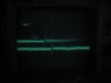
By the way, slightly off topic, but interesting...on the amp I'm currently building I am investigating power transformer ring. Here's a pic of the ring with no damper circuit across the secondary. (Image is hard to capture and has a ghost trace behind the real one given the slow shutter speed I needed to use). This is at 10x magnification with 2 mV per vertical division and 5 ms per horizontal division.
And here's the same shot with a 0.1 uF cap in series with a 220 ohm resistor across the secondary, everything else is the same between the two pics.
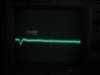
So this clearly shows the effect of LC induced ring on the secondary when the diodes flip on and off, and the ability to damp it out almost to nil.
And here's the same shot with a 0.1 uF cap in series with a 220 ohm resistor across the secondary, everything else is the same between the two pics.
So this clearly shows the effect of LC induced ring on the secondary when the diodes flip on and off, and the ability to damp it out almost to nil.
Schmidlapper
Super Member
Snubbers definitely have a useful purpose. I love what it did for my big solid state power amp and pre amp.
Good news on the transformers, I sat down this morning and retested all the taps and found I have a 7.2k tap for an 8 ohm load which according to 6V6 RCA tube data sheet is almost ideal plate to plate load for push pull at my 297 plate voltage. Also found some supporting data for what I saw in the initial test in the amp. Transformer 8 ohm reflected load tested 7.2k at 1KHz and at 20KHz, but then tested 4.6k at 50Hz. So that may explain the lower max voltage I got for a nice clean 50Hz sine wave. Interestingly a 1KHz sqaurewave is a 16.9K reflected load.
Edit: Correction: I made a procedural mistake regarding the 50HZ and square wave results so they are nonsense, I realized that I had not re-verified the input voltage for those readings, and they likely are just reflecting a frequency related voltage differences in my source.
Now I need to figure how best to install these things on the 8802, and then I will get to sorting out the feedback resister. I think initialIy I had the primary leads backwards as I was getting a choppy weird scope picture until I clipped out the feedback. From what I understand I may have been adding positive feedback if backwards, which does look crazy.
Good news on the transformers, I sat down this morning and retested all the taps and found I have a 7.2k tap for an 8 ohm load which according to 6V6 RCA tube data sheet is almost ideal plate to plate load for push pull at my 297 plate voltage. Also found some supporting data for what I saw in the initial test in the amp. Transformer 8 ohm reflected load tested 7.2k at 1KHz and at 20KHz, but then tested 4.6k at 50Hz. So that may explain the lower max voltage I got for a nice clean 50Hz sine wave. Interestingly a 1KHz sqaurewave is a 16.9K reflected load.
Edit: Correction: I made a procedural mistake regarding the 50HZ and square wave results so they are nonsense, I realized that I had not re-verified the input voltage for those readings, and they likely are just reflecting a frequency related voltage differences in my source.
Now I need to figure how best to install these things on the 8802, and then I will get to sorting out the feedback resister. I think initialIy I had the primary leads backwards as I was getting a choppy weird scope picture until I clipped out the feedback. From what I understand I may have been adding positive feedback if backwards, which does look crazy.
Last edited:

Keep in mind, all datasheet voltages are measured from cathode, from ground. Figure 15-20v of cathode voltage and you're closer to 280v across the tube.
Unless we're talking fixed bias, in which case cathode is probably at ground potential or near enough as to not matter.
Positive feedback makes things go absolutely nuts. When I converted my German console amp to actually have a complete feedback loop, it was backwards. Not sure if it originally tied in to a stage in the preamp, or if it just never had any feedback but either way I had to reverse it so it worked properly. It made a really spectacular oscillator at first. I'm glad it was on the dummy load and not speakers.
Unless we're talking fixed bias, in which case cathode is probably at ground potential or near enough as to not matter.
Positive feedback makes things go absolutely nuts. When I converted my German console amp to actually have a complete feedback loop, it was backwards. Not sure if it originally tied in to a stage in the preamp, or if it just never had any feedback but either way I had to reverse it so it worked properly. It made a really spectacular oscillator at first. I'm glad it was on the dummy load and not speakers.
Schmidlapper
Super Member
I'm using split channel cathode, 360 ohms each with 220uF bypass each. If I'm getting the voltage drops you mention, It would still be my closest tap to ~8K. I will measure later to verify. Appreciate your always useful input. In fact I'm going to reference a PM I have from you containing a gain formula using open and closed loop measurements.
I was able to locate and drill the new mounting holes for the transformers before I needed to leave to get my vehicle worked on. They fit quite well. Pictures will come once I have chance to bolt them down. I will need to order new binding posts so I can relocate them from the top to the back through the wood surround. I will just use some jumpers in the meantime.
I was able to locate and drill the new mounting holes for the transformers before I needed to leave to get my vehicle worked on. They fit quite well. Pictures will come once I have chance to bolt them down. I will need to order new binding posts so I can relocate them from the top to the back through the wood surround. I will just use some jumpers in the meantime.
Schmidlapper
Super Member
What the hell is an Odyssey
What the hell is an Odyssey
A poem by Homer?
Schmidlapper
Super Member
That was supposed to go out in a text, I wondered where it disappeared to. I'm doing to many things at once. It was actually a very funny response to a question that will be forever lost
Schmidlapper
Super Member
So as I sit here still waiting for my car to get done I ponder, initial state 2200/380 feedback ratio for 6k reflected load. I'm changing to a 7.2k reflected load, all else being equal am I going to start out going higher or lower for Rf?