• The move to the new server is done. There are some software and database maintenance updates in process. This has us passing the hat around to help out. We appreciate any donations. Seriously, even a dollar helps. The payment page may be found here - https://www.audiokarma.org/support.html

7189 Monoblock Project

CoolOhm

Cool Ohm
Hello:

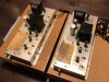
I am posting this in the hopes someone can shed some light on some nice old iron I just acquired. I have two nice PTs and two nice ultralinear OPTs, all pulled from two mono 6BQ5 ∕ 7189 amps. These were taken from organs from the early sixties. The amps have 6GH8s and EL84s in push-pull. I removed the transformers today and the center-tapped PT produces 510V on each of the red wires relative to the centre tap with 124 VAC applied to the two black primary wires. My plan is to build a pair of monoblocks based on the Sherwood S-5000 schematic with this iron.

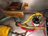
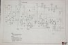
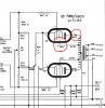
I do not have a schematic of the donor amps but I do have a similar schematic from the same era, by the same manufacturer (Electrohome). That schematic shows 4, 8, and 16 Ohm secondary taps on the OPTs. As you can see from the photo posted, there are only three secondary wires. So to develop the circuit, I need to figure out what these taps are because the circuit I hope to use takes NFB from the 16 Ohm tap. I am not even sure I have that tap.
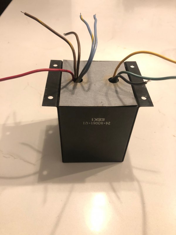

So I connected a variac to the OPT primaries (blue and brown) and determined the turns ratio which is 29. The possible reflected impedances correponding to 4, 8, and 16 Ohms are 3364, 6728, 13456 Ohm, respectively. Looking at the 7189 and EL84 datasheets, under pentode connected UL operation I read 11 kOhms, plate to plate. To be precise, I was applying 29 VAC to the secondary plate supply wires (blue and brown), whilst measuring 1 VAC between the green and black secondary. At the same time, black and yellow gave 0.71 V and green to yellow gave 0.29 V. The DC resistances I measured on the secondaries were 1.9 Ohms (black to green) and 1.5 Ohms (black to yellow).

Can I conclude from this that since 13456 is closer to 11000 than 6728, that the secondary tap with the largest impedance is a 16 Ohm tap (black to green) and that the other tap (black to yellow) would be an 8 Ohm tap? From looking around on the net it seems rare those old transformers had just three secondary wires. Would it be more common to see 16 and 8 than 8 and 4 in such a case?

As usual, any insight would be hugely appreciated!

Thank you!

David
 
Register to hide this ad
What organs were the amps pulled from? If you know that you can look for a schematic. That info will save you lots of time.

Numbers stamped on the transformers might also help with identifying them.
 
Hi Dandy.

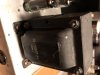
Thanks for the suggestion. As far as I can tell they were called 'Concertina' and also 'Nocturne'. Made by Electrohome in Canada for the New Jersey Kinsmen company. I spent weeks looking and all I came up with is attached. It is close, but it is not the correct schematic. It shows four wires, and as you can see, I have three. I need to use another method to identify these transformers. The markings on the transformers yields nothing from internet searches. Someone well versed in transformers might know how to decipĥer them, but I cannot. The choke, PT, and OPT all seem to share the same numbering system, but again searches don't generate anything.

choke: 24-110021-01 EEK1
OPT: 24-80061-01 EEK1
PT: 24-10077-01 EEK1

Take a look, see what you think...

Best regards,

D1_Both.jpg 3_PT.jpg 5_Choke.jpg electrohome_7189_e84l_monoblocks.jpg
 
Pending review of my math by those more knowledgeable, it seems to me that you have a 4 and an 8 ohm winding on the secondary. 29/.71 give you a turns ratio of about 40.85. Square that and we get an impedance ratio of 1668. 1668x4 gives us just about 6.7k ohms so very close to the 8 ohm claculation.

I'd have to do some digging to verify but I'd be willing to bet that the original Sherwood transformers that the schematic you want to use is based on, were much closer to 6.7K impedance than to 13K.

Also, as pertains to your power transformer measurements, are you saying that the winding measures 510 AC volts from end to end or from center tap to either end? If as I suspect, your transformer is 255-0-255, you will not have sufficiently high voltage to be able to clone that Sherwood circuit.
 
Pending review of my math by those more knowledgeable, it seems to me that you have a 4 and an 8 ohm winding on the secondary. 29/.71 give you a turns ratio of about 40.85. Square that and we get an impedance ratio of 1668. 1668x4 gives us just about 6.7k ohms so very close to the 8 ohm claculation.

I'd have to do some digging to verify but I'd be willing to bet that the original Sherwood transformers that the schematic you want to use is based on, were much closer to 6.7K impedance than to 13K.

Also, as pertains to your power transformer measurements, are you saying that the winding measures 510 AC volts from end to end or from center tap to either end? If as I suspect, your transformer is 255-0-255, you will not have sufficiently high voltage to be able to clone that Sherwood circuit.


Hi. Thanks. No 510 was tap to centre. From end to end was over 1000 V. Both my meters were unhappy with that!

Also, I am not sure about the 29 divided by 0.71... I measured 29 as the turns ratio by energizing the primary windings with 29V that gave exactly 1.0 V on the secondary. So 29 squared is 841. 8 Ohms x 841 would suggest 6728 Ohms in the primary windings. So another possibility is that these are 4 and 8 Ohm taps on the secondary side.

Best regards,

D
 
Last edited:
There may some useful information in this post on The Organ Forum: https://organforum.com/forums/forum...32109-electrohome-kinsman-concerto-schematics

Specifically:
that this model (Electrohome Kinsman Concerto) is the same circuit as the "Rhapsody" and "Nocturne" models, ... except in different cabinet styles.
The voltages are different from what you're measuring unloaded (but your PT might be designed to supply a lot of tubes). "... the Kinsman designs that I know of simply use two 0A2s in series to give 300V, with no adjustment possible." That voltage wouldn't make it worth using 7189 tubes and as Kidmoe says is not high enough for the Sherwood design.

Also, the Sherwood S-5000 II does not use UL taps, so there's another difference.

If you still have the original amps, why not reinstall the transformers and get the amps going as they are, to see what you've got in terms of voltages?
 
Hi Dandy:

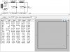
Thanks. Yes I have both amps, one is untouched. I will for sure measure the voltages, but the power supply is not really my concern as I would prefer to use SS rectification. I know I can get 510 V per side, and the Sherwood S-5000 schematic shows 420 V at the anode and 424 at the screen connection (the S-5000 uses UL taps). Check out the image below.

My first priority is actually the presence or absence of a 16 Ohm secondary tap, as for now I am unsure - but I know the S-5000 uses negative feedback taken from the 16 Ohm tap.

PS_Clip.JPG

Best regards,

David
 
You should also validate that the leads you've selected on the primary are in fact the plate leads. You can validate the primary lead orientation by driving the transformer backwards. Put say 5VAC between the yellow and black leads. That should put about 145V AC on the primary between the leads you expect are the plate leads. But then, while keeping one volt meter probe fixed on its primary lead, move the other volt meter probe to the other available primary leads and see what you measure. If you have the plate leads properly identified, you will measure less voltage than 145V on every other available primary lead. You can also use this technique to identify which screen tap lead pairs with which plate lead. You should not assume the lead color gives you this information.

Assuming you've got the primary plate leads correctly identified, the other issue to consider is perhaps the manufacturer spec'd the output transformers for an odd secondary impedance. For example 10 and 5 ohms instead of 8 and 4 ohms. So if the yellow tap represents 10 ohms, it would reflect 8.4K to the primary, as an example.

Because the voltage ratio between black-to-yellow and black-to-green is 0.71 (inverse of root 2), the impedance ratio between those two is 0.5. So whatever impedance exists between black and yellow, the impedance between black and green must be 0.5 of that (assuming your voltage ratio measurements are correct).

With silicon rectification, 510V unloaded voltage on the power transformer secondaries, and assuming 90% power transformer regulation at the "smallish" current each amp will require, that's still going to give you right around 600V DC B+ as your feed point to the output stage--that is if you use capacitor input filtering. You don't want to voltage drop that down with a resistive divider since the performance of the amp will suffer substantially. You want a low impedance power supply to effectively drive the output stage. If you use a 5U4GB rectifier, that will knock that down to something like 525V B+, and that might be doable...but it's still about 125V over max design center rating for 7189 tubes.

My opinion is with silicon rectification, it would be better to use a different power transformer, say 360-0-360, so your tap point to the output stage would sit at approximately 475V DC. That will deliver a low impedance voltage source to your output stage and it should work fine with 7189 tubes, even if still over design center max rating. But if you bias the output stage somewhat cool, it should work.
 
Also, I am not sure about the 29 divided by 0.71... I measured 29 as the turns ratio by energizing the primary windings with 29V that gave exactly 1.0 V on the secondary. So 29 squared is 841. 8 Ohms x 841 would suggest 6728 Ohms in the primary windings. So another possibility is that these are 4 and 8 Ohm taps on the secondary side.

You mentioned that you got 1 Volt out at the green-black secondary winding when applying 29 Volts to the primary, that would be your 6.7K 8 ohms . You also got .71 Volts out of the yellow-black winding using the same 29 Volts at the primary. Simple math as shown above says that this would have an impedance ratio of 1668:1, so then we ask ourselves what seems more logical; that this is a 4 ohm tap at about 6.7K ohms impedance or a 16 ohm tap at 27K impedance?
 
Mocking up a transformer that puts out 510V shows that without the use of very heavy duty dropping resistors, you would actually have over 650V at the takeoff point to the output transformer, way too much.

2huU2gz.png


Going with an LC filter would give you just about the voltage that you would want, about 435V to the output transformer but that would be one heck of a choke.

EdHqlLE.png
 
Last edited:
As well, since your OPTs are not UL devices, you will need some method of dropping the screen voltage down to about 300 DVD as you would not want to operate them in pentode mode at the same voltage that they are operated at in the S-5000 in UL mode.

Dave
 
Hi. Thanks. No 510 was tap to centre. From end to end was over 1000 V. Both my meters were unhappy with that!

Also, I am not sure about the 29 divided by 0.71... I measured 29 as the turns ratio by energizing the primary windings with 29V that gave exactly 1.0 V on the secondary. So 29 squared is 841. 8 Ohms x 841 would suggest 6728 Ohms in the primary windings. So another possibility is that these are 4 and 8 Ohm taps on the secondary side.

Best regards,

D

You will need a choke-input power supply, for that power transformer to work. Here's a quick sim of that:

electrohome_organ_pt_power_supply_L_input.jpg

You can get a little more B+ voltage, by using solid-state diodes. Be aware that the rectifier, whether it be tube or SS, will need to handle 1500V peak. That means if you used a diode like a 1N4007- you need to connect two in series.

Also, you will need at least 600V rated power supply caps- this is due to the fact that a choke-filtered supply doesn't regulate, until there's a load. With a proper bleeder resistor to establish a little bit of initial current at startup (6ma or so) until the output tubes come up, the peak voltage will be just over 600V, for a short enough period of time that 600V caps should be fine.

Regards,
Gordon.
 
A little better voltage for a 7189- modeling with a 5R4 rectifier, and a Hammond 158M choke in the first position, and a Hammond 154M choke in the second position:

electrohome_organ_pt_power_supply_L_input.jpg

Regards,
Gordon.
 
As well, since your OPTs are not UL devices, you will need some method of dropping the screen voltage down to about 300 DVD as you would not want to operate them in pentode mode at the same voltage that they are operated at in the S-5000 in UL mode.

Dave

I have done this, by using zener diodes in series with the screen feed.

If the PS I modeled above was used, you could use two 56V, 5 watt zener diodes in series, wired between the plate supply cap and screen supply cap, to get a 112V drop. That would give about 298V on the screens. I would put something like a 220 ohm or 470 ohm 1 watt resistor in series with the Zeners, to damp out any Zener noise and give the screen supply cap something to filter from, too. Of course, it goes without saying, with such a stiff screen supply- you'd want to put screen stability resistors on the output tubes- something like 220 ohms would be fine.

Regards,
Gordon.
 
The OP says in his original post that his output transformers are UL capable so he should be able to connect UL without dropping all that voltage as long as he can get the power transformer voltage under control.
 
Thanks Kidmoe and Kward for bringing up the use of a dropping resistor in the power supply. I was unaware that is a no-no for good performance. Thanks also to Gordon for furthering that simulation.

Taking Dandy’s suggestion, I powered up the one amp I did not touch last night. Between chassis and pin 7, I measured 400 VDC. On pin 9 I measured 410 VDC. So I will either stick with the 5V4s, or purchase new PTs if I need go the solid state route.

Kward – thanks for the suggestions. There really is not much uncertainty in the leads. I have the amps in my possession and I can clearly see the pairs of primary leads and how they are wired to the tube sockets. I can also clearly see the black secondary lead connected to chassis ground.

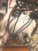
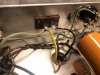
Also if you take a look at the schematic (the one I did manage to find, and appears to very close to my amps), the biggest differences I see are the 12AX7s instead of the 7687s in the driver-splitter, and the four secondary OPT wires instead of three. Of note, the schematic shows the 16 Ohm wire connected only to the ‘tone cabinet’ connector, pin 2. My amps have the green secondary connected only to the ‘tone cabinet’ connector, pin 2. The schematic shows the 8 Ohm wire to the Leslie connector and to pin 4 of the tone cabinet with the 4 Ohm wire connected to the organ speaker and NFB. My amps don’t have the Leslie connector, and the yellow wire is connected to the organ speaker and NFB. Pictures are attached corresponding to all of these observations. In my original post, I referred to but did not post the schematic. It is of poor quality (my apologies), but it is now attached. I am also posting a picture of a layout sticker on the top of the amps.

Prim Leads.jpg Sec Leads.jpg Label.jpg electrohome_7189.jpg

Dave, thank you for your comments. Why do you (or did you) presume the OPTs are not UL devices? My reasons for assuming they were are that they were sold to me on that basis (no guarantee, admittedly) and also the schematic, and the tube wiring. But I have been poking around these forums long enough to know better than to take your comments lightly... If these are not UL then I will likely cancel the whole project!

Another question I have would be the possibility of adding triode-UL switches to the Sherwood S-5000 schematic... That is an option I find appealing and I wonder if there are any reasons not to do so...

Again – thanks everyone!

D
 
Just out of curiosity, the working amp that you tested to get those numbers, is it currently powering only a pair of 7189 tubes and the driver tubes? If so I'd be interested to see what mechanism is being used to drop 225-250V from the 510-0-510 power transformer B+ to arrive at 400V on the 7189 plates.
 
Just out of curiosity, the working amp that you tested to get those numbers, is it currently powering only a pair of 7189 tubes and the driver tubes? If so I'd be interested to see what mechanism is being used to drop 225-250V from the 510-0-510 power transformer B+ to arrive at 400V on the 7189 plates.

Strangely enough the seller cautioned me not use EL84s in these as they cannot take the higher voltages, yet they arrived with EL84s in them (most of them illegible). Last night when I powered it up I was getting 385 VDC right off the 5V4, and about the same on the lower tube anode, I checked the secondary connections into the 5V4 and read something in the high 900's VAC. I noticed something was humming, took a peek and noticed one power tube seriously red plating so I yanked the power chord. Turns out there was a 6CW5 in that position. Swapping it with another EL84 lead to the 400, and 410 VDC measurements, all happy - no hum. I did not repeat the measurement at the 5V4. But reading the 5V4 data sheet, these values seem where they should be. There is a big choke connected to the multi-cap, but I do not know the inductance value. See excerpt from the datasheet.

Sorry - I should also add that everything was powered up (all the tubes indicated on the service label).
 

Attachments

  • 5v4-p2.gif
    5v4-p2.gif
    9.1 KB · Views: 4
OK. For the sake of clarity, I'm curious what you get for a reading between either end of the red high Voltage winding and the red/striped center tap that is grounded with all the tubes removed and amp turned on. I think maybe some of us that were trying to model you're power supply for you were assuming that your 510V reading in your original post was an unloaded value whereas I'm starting to think know that you got that reading with the circuit loaded down.
 
OK. For the sake of clarity, I'm curious what you get for a reading between either end of the red high Voltage winding and the red/striped center tap that is grounded with all the tubes removed and amp turned on. I think maybe some of us that were trying to model you're power supply for you were assuming that your 510V reading in your original post was an unloaded value whereas I'm starting to think know that you got that reading with the circuit loaded down.


Certainly! The 510 VAC value was unloaded, with removed PT on the bench. I chose this route initially as I did not have a variac and did not want to risk plugging in these old amps, especially considering a complete re-build is inevitable (turns out my intuition was correct, considering the discovery of the 6CW5). But I got stuck on the problem of the missing secondary tap and had not choice but to bight the bullet and get one for the purpose of gently powering up the primaries of the OPTs to determine the turns ratio. Luckily there was a used one available cheap.

Thanks again for your interest and comments.

D
 
Back
Top Bottom