• The move to the new server is done. There are some software and database maintenance updates in process. This has us passing the hat around to help out. We appreciate any donations. Seriously, even a dollar helps. The payment page may be found here - https://www.audiokarma.org/support.html

7591' s hot in The Fisher 800C

fquevedob

New Member
Hello. I'm new here and I'm having problems. I recently purchased a The Fisher 800C. It's a hard device to find in Brazil. Two 7591s are getting very hot. When I change them from one channel (right to left), they continue to heat up and make the transformer heat up even more. So it seems that the problem is with them. Any suggestions? Thanks.
#thefisher #thefisher800c
 
Register to hide this ad
The 800C appears to be a cathode biased amp (power tube bias is not adjustable via a pot). Am assuming the other pair of tubes is not getting too hot when installed in the right or left channel. So, sounds like the pair of tubes that is getting hot in either channel has may have one or two bad tubes that are starting to have a runaway (red plate).
 
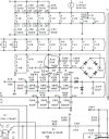
The 800C is a fixed bias amp where the bias is set to -17V and is not adjustable. You can verify that the bias voltage is correct if you have a meter, check the voltage on pin #6 on each of the output (7591) tubes to conform the bias is at or near -17V. You can download the service manual for your particular 800C with the following link:


If the bias voltage is incorrect use the schematic to trace the bias circuit to find where the voltage shifts.
 
The 800C is a fixed bias amp where the bias is set to -17V and is not adjustable.

It is confusing, but "fixed bias" means the bias is adjustable via a pot in the amp.

"In fixed bias amplifiers, once set, the bias does NOT move up and down automatically. And that's where the 'fixed' bit comes in. For your interest, all preamp valves (like ECC83s) are cathode biased. This is why you never have to bias them. Cathode bias is a kind of self-bias circuit."
 
But some fixed bias circuits are truly fixed - no adjustment provided. This is one. If you're using modern (Russian) 7591, modification more negative bias voltage is needed - might as well add a bias adjustment.
 
I'm using the original Fisher 7591s. Another thing, the receiver is 110 V and in Brazil the current is either 220 or 127 V (I'm using a converter for 127 V).
 
I’m with Tom here. For future piece of mind regarding the costly 7591’s, look into and install a bias adjustment. In the end, what you’re concerned about dissipation of the tubes. The bogey standard is -17vdc but the operating voltage will depend on the health/manufacture of the tubes. That’s where the adjustment modification comes in. Fisher designed around a single resistor to accomplish this. Today, with tube cost, wall voltage, and limited tube choices, regulating the bias voltage is the preferred way to avoid losing tubes, or worse, a transformer.

There are tons of restoration threads in the Fisher forum. You’d be well served to read up on your receiver as that will give you much to think about.

In the meantime, identify the bias resistor in your unit, remove it and install a single 10k trimming pot. That will permit you to dial your bias to a more appropriate level while you decide upon a more permanent solution.

Good luck and welcome!

 
I'm using the original Fisher 7591s. Another thing, the receiver is 110 V and in Brazil the current is either 220 or 127 V (I'm using a converter for 127 V).

In doing your research, also look into “bucking” transformer. Fairly easy to build yourself.
 
I'm using the original Fisher 7591s. Another thing, the receiver is 110 V and in Brazil the current is either 220 or 127 V (I'm using a converter for 127 V).

127 is pretty hot for the Fisher. Can you source a 220V to 110 step down transformer?

as others have noted, you may want to measure the bias and see what value you are getting. You could have a problem of high B+ (due to the 127VAC input in addition to a hot bias setting which would give you the hot tubes.
 
The heater circuit will tell you if the line voltage is too high. It should be 6.3 vac +/- 5% for a happy amp. If its outside that, the line voltage needs tweaking to fix it.
 
I’m with Tom here. For future piece of mind regarding the costly 7591’s, look into and install a bias adjustment. In the end, what you’re concerned about dissipation of the tubes. The bogey standard is -17vdc but the operating voltage will depend on the health/manufacture of the tubes. That’s where the adjustment modification comes in. Fisher designed around a single resistor to accomplish this. Today, with tube cost, wall voltage, and limited tube choices, regulating the bias voltage is the preferred way to avoid losing tubes, or worse, a transformer.

There are tons of restoration threads in the Fisher forum. You’d be well served to read up on your receiver as that will give you much to think about.

In the meantime, identify the bias resistor in your unit, remove it and install a single 10k trimming pot. That will permit you to dial your bias to a more appropriate level while you decide upon a more permanent solution.

Good luck and welcome!
I looked for a schematic for changing the bias resistor and installing the single 10k trimming pot. Is there a schematic for this? Thanks.
 
Sub the 5.6k with a 5k pot in series with a 2.2k resistor. That should put center travel of the pot basically at stock bias point and give a pretty good range of adjustment. If thats too touchy, a 2.5k pot in series with a 4.7k resistor will also work, but with less range. All depends what you've got on hand.

either way if the pot fails open, you get max negative grid voltage rather than no grid voltage.

This moves all 4 tubes at once though so if you have poorly matched tubes its not really going to fix it. You'll have to shuffle things around and come up with the best compromise. I would add the 10 ohm cathode resistors here so you can figure out how much current the tube is pulling.
 
You’re going to have to add resistors at the power tube location in order to measure the bias voltage going to the tubes. These would be 10ohm 1/4watt resistors at each tube.

At each 7591, there’s a jumper from pin5 to ground. Clip the jumper and install the resistor in its place. The resistor doesn’t affect the sound but allows you to measure the bias current to the respective tube. Set the trimmer to hottest tube.

You might want to consider posting for advice in the Fisher forum. There you’ll find very helpful folks who are Fisher aficionados and whose experiences can positively guide you.
 
Back
Top Bottom