• The move to the new server is done. There are some software and database maintenance updates in process. This has us passing the hat around to help out. We appreciate any donations. Seriously, even a dollar helps. The payment page may be found here - https://www.audiokarma.org/support.html

8 ohm L-Pads for AR speakers

JoeTTD

New Member
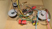
I need some help in understanding the "correct" value of resistor to insert when using (2) 8 ohm L-pads in an AR-5 crossover. From what I read I have inserted a 25 ohm 10 watt resistor across terminals 1 and 3. When I measure the resistance of the original AR pot I get 15.9 ohms across the whole range of settings. If I measure the L-pad with a 25 ohm resistor (Dayton Audio Precision 10w 1%) across terminals 1 and 3, I get a minimum of 6.3 ohms to a maximum of 25.3 ohms. But if I put a 16 ohm resistor in the same spot I get a minimum reading of 5.2 ohms and a maximum of 16.1 ohms. Doesn't the 16 ohm resistor come closer to the original maximum value? Which is the better value to use and how will the two different values affect the sound from the midrange and tweeter? Will the 16 ohm resistor give a louder sound to the mid and tweeter compared to the 25 ohm resistor? And if I use no resistors on the L-pads how will that affect the sound?

 

Attachments

  • 002.JPG
    002.JPG
    111.9 KB · Views: 22
Register to hide this ad
Don't have an answer to which (if any) resistor value is better across the L-pad, but the questions stoked my curiosity enough for some casual exploring. Began with a basic look at similarities and differences between potentiometer and L-pad.

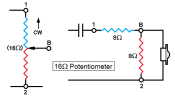
Pot as a voltage divider has a single resistive element divided by the wiper into series resistance and parallel resistance:
16 Ohm Pot C.png
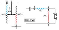
Eight Ω L-pad has separate series element of 8Ω and parallel element of 40Ω that divides voltage at much different ratios through rotation than a pot:

8 Ohm l-pad C.png
Took a few measures of an L-pad with added shunt resistors to confirm I'm seeing the same as you:
Three Meas x 3.JPG

Close enough!

Then ran simulations in Xsim for a general feel of response difference between 16Ω pot and 8Ω L-pad with 16Ω, 25Ω or no shunt resistor.

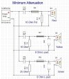
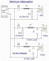
Simulated a tweeter circuit and first examined minimum attenuation (max output level) using the potentiometer or L-pad with either 16Ω or 25Ω shunts:

Min Atten.JPG
Note that the 16Ω pot circuit and 8Ω L-pad/16Ω shunt circuit are electrically identical. At minimum attenuation the L-pad is bypassed (series resistance shorted and parallel resistance open), leaving only the shunt resister in play. Which is exactly what a 16Ω pot is at minimum attention. The pot's red response plot is completely hidden under the identical yellow plot for L-pad/16Ω shunt.

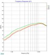
Also, shunt resistors of 16Ω and 25Ω track very close -- just over 1dB between them at lower frequencies.
Min Atten Gr.JPG
Note that the 25Ω shunt resistor plot (green) has the slighty higher output. That's expected -- higher shunt resistance allows less signal to be "siphoned off to ground."

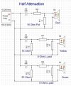
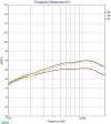
Pot vs L-pad becomes more dramatic in half attenuation simulation:
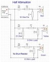
Half Atten.JPG
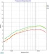
Half Attn Gr.JPG
Now L-pad/16Ω shunt combo (yellow) no longer resembles the pot (red). L-pad versions track significantly higher output, with 25Ω shunt version still highest for reason stated.
 
Next compared response between pot, L-pad with 25Ω shunt and also with no shunt resister. Started with minimum attenuation.

Min-no-shunt.JPG
Not surprising that the shunt-free L-pad version (green) has highest output. Pot (red) and L-pad/25Ω shunt version (yellow) track close just as they did prior.

Min-no-shunt-Gr.JPG

Ran these same through half attenuation:

Half-no-shunt.JPG
Half-no-shunt-Gr.JPG

These results suggest that running an L-pad with no shunt resistor will increase output through lower frequencies of the driver's bandwidth, but then converge at the higher end with L-pad having a shunt resistor.

Since L-pads allow for higher output at low attenuation settings, maybe the shunt resistors are intended to pull down this extra energy in the lower frequencies of tweeter and mid bandwidth. Notice how the L-pad with shunt resistor (yellow) tracks close to the potentiometer (red) at lower frequencies, then rises to meet the un-shunted L-pad response in the upper bandwidth.

All just guesses on my part. But maybe this offers some ideas, at least, about general differences between attenuation configurations for AR-5.
 
Last edited:
Just found a reference to the reason for using shunt resistance when substituting L-pads for original 16Ω pots. Should've checked "Similar Threads" below in the first place ...:p

@RoyC, renowned guru, explains it thusly:

"L-pads, compared to the original pots, allow more output at all levels, and would work fine if it weren't for the fact that they also alter (lower) the crossover points. The parallel resistors compensate for this and electrically make them act like the pots in the first 1/3 to 1/2 of the l-pads' rotation off maximum (which is where most users set them)."
 
Stuart, thank you for that technical response. I stayed with the L-pads and the 25 ohm resistors. Seems to work fine in that configuration, especially at 1/2 rotation.
 
Back
Top Bottom