• The move to the new server is done. There are some software and database maintenance updates in process. This has us passing the hat around to help out. We appreciate any donations. Seriously, even a dollar helps. The payment page may be found here - https://www.audiokarma.org/support.html

800C volume & on/off switch replacement

rufleruf

Preserving the sound
All,

I'm going through my projects figuring out what parts/repairs everybody needs and making a list of parts, tubes etc to keep an eye out for.

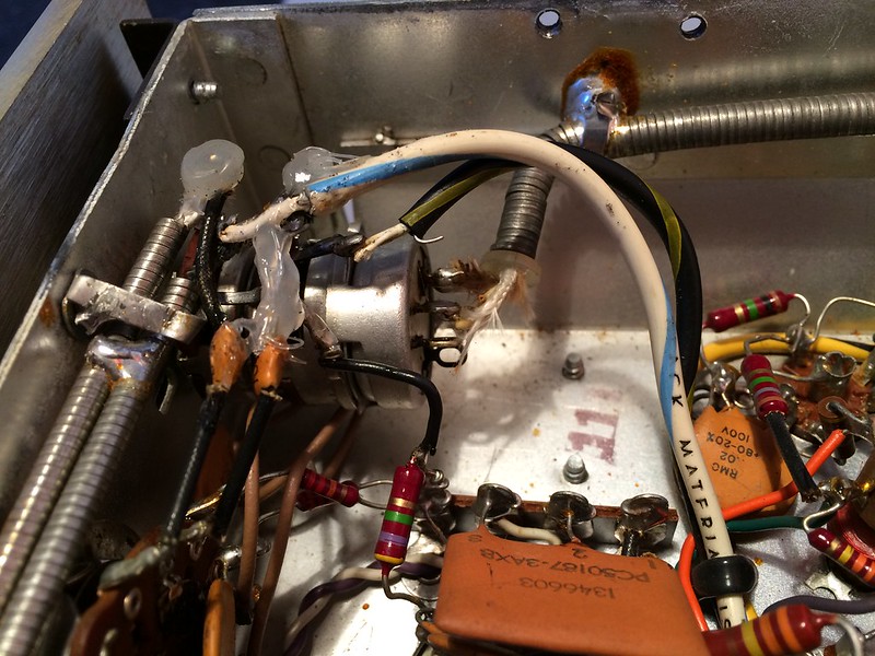
My 800C has the distinction of having had the volume/on-off pot changed out at some point with a part obviously not meant for the Fisher, has a ribbed shaft thats been filed down and cut to a "D". It's a 2 pot with on-off switch like the original, but looks different and is all wired in. I have no idea if it ever worked with this switch installed. To make matters worse (I can't test and maybe it works), when I was test fitting caps for it, the whole shaft pulled out!

There are three directions I can take here: 1. get an NOS or used replacement and make it right; 2. try and make the switch that is installed work; and 3. try and find a suitable new replacement. Well, there is a fourth, but this thing is WAY too nice to cannibalize.

So, 1. is the safe road, just need to beg for parts on bartertown or watch ebay for Fisher parts or the holy grail, a Centralab NOS replacement (anyone have a part number?).

2. is probably a big time suck -especially if something like the swept range is off!

3. is at this point unknown. I can't think of very many modern electronics that build the volume pot and on/off switch together -I have a Korg synthesizer that does, but it's rare and 35 years old so that hardly helps. I think down the road though, that as these receivers age and become more valuable (I think they will), the only solution will be new replacements. With this, and all the threads about imbalanced sound due to volume pots that came up when I searched to see if anyone had ever come up with a suitable modern replacement in mind, I ask:has anyone done the research or found a suitable replacement?

Post a link if this has been beat to death somewhere and I just didn't find it!

 
Register to hide this ad
You can get single pots with a switch
You can get dual pots
You can get dual pots with a loudness tap...but...

I don't think you'll find the combination of dual pot and switch.

So you can replace the pot with one without a switch (install a slide or rocker switch in place of one of the AC outlets - they're usually broken anyway). My 800C had the AM bandwidth switch rewired as a power switch.

Or you can see if Mark Oppat can make one for you: http://oldradioparts.net/controls.html

And whatever you do, install an inrush limiter so that the switch will last.
 
I just found this from a 2002, audio asylum thread:

"I had the same problem on my 500b. I looked everywhere but no luck. The issue is of course, is finding a dual 500k pot with an AC on/off switch. I finally had a pot custom made from State Electronics. However, the pot cost >$50 for just one. I believe best price was around $30 for qty of 50. Well, the 500b sounds great, however, I think I will settle on just a volume pot next time with an external on/off switch."

I'm going to contact State and see if they can still make these. If they can, maybe a group buy could be arranged. Seems worthwhile?
 
Uh... Matt, the 31-R has the 2 gang with switch, and it might be the same era as your 800C

Still looking for a box

Rick
 
Rick,

I was hoping it did, and from the pictures it does look that way. Problem is I will ultimately need a few of them, and it seems like it would benefit the community if there was a known supplier for this part new -especially considering there are known audio performance issues associated with these pots.

Might even help keep more otherwise viable 400/500/800 and other Fisher receivers of this era that need this part from getting parted out due to having had theirs removed.
 
If I don't get anywhere having a replacement made, I will probably go the Alps route.

I'm in contact with State Electronics right now discussing the requirements of the new switch. I am hoping we can come up with a drop in replacement with no need to modify any other part of the receiver.

If someone has an exhaustive list of measurements and requirements in front of them they can post, it would be helpful. I don't have any of these pot/switches out of a unit right now.
 
Don't limit your search to the 800-C. The 500-C and 400 have the same switch/pot unit and IIRC the 500-800/B does also. The newer Solid state receivers like the 31-R have a shorter shaft by 1/2" to 5/8".

The FISHER part # in the FISHER SERVICE MANUAL is actually a CENTRALAB #.
 
Don't limit your search to the 800-C. The 500-C and 400 have the same switch/pot unit and IIRC the 500-800/B does also. The newer Solid state receivers like the 31-R have a shorter shaft by 1/2" to 5/8".

The FISHER part # in the FISHER SERVICE MANUAL is actually a CENTRALAB #.

I was aware that all the 500/500/800 switches are the same from a cross reference spreadsheet I made, I was not aware that the Fisher PN is also the Centralab PN. Good to know.

I pulled out two switches last night for comparison. A very clean one from a low miles rusty 400, and a well worn one without an on/off switch from a high miles but clean 800B. Same PN's but slightly different construction.

My average in various positions for the loudness tap on the nicer pots is about 350K, for the well worn one, about 290K. I don't see a spec on the schematic, should I assume 350K is a good value for the loudness taps?

I took readings at 6, 9, 12, 3 (o'clocks) then max, and the resistance on the well worn switch falls off more quickly than the newer one and has greater variation (at 9 o'clock the worn switch has 370K front and 470K for example; then at 12 o'clock the newer one is 0.34/0.37 while the worn is 0.24/0.24). I checked each position several times at the same contact points.

I'm only trying to get an idea of what these do, not make any point, and I though some of you might find this interesting.

I'm really hoping someone will chime in with a good value for the loudness tap to give builder of my new switch.
 
Bruce,

I talked to State today and it's a no-go. I am going to reach out to Alpha next. I work as an engineer for a globally recognized company, so when I make inquiries, I tend to get a fast and well considered response.

As a plan B, and sort of in conjunction with my reaching out to Alpha I ordered 6 of their dual 500K audio pots, 6 of their single pots with an on-off switch and correct length D shaft, some conductive paint and .5mm PCB hollow rivets. I'm sure you can guess what I'm planning - make my own loudness taps! I will probably shoot for a value that can work in series with a variable pot to help tune the volume circuit. I'll post results when all the parts come in and I get a chance to try and MacGyver one together. I expect the switch is only rated for triggering a relay, but even so, this could be a drop in DIY switch with modern parts, and if they have all the sub-components to put together a real replacement with only the addition of a 150K tap and a higher rated switch, they might put it in production. Based on the cost of all the stuff I ordered today, it could be less than $10.

I pulled out the switch that sent me down this road and it's a Mallory that measures to be the correct type. I guess I'll see if I can get it to work.
 
The volume control and switch on these guys are its weakest links IMO. Good luck on your McGyver pot :thmbsp:
 
Ruf -- To help you in your quest, and based on the great number of these controls that I have come into contact with, I would offer these considerations:

1. The controls are specified as a 500K control, but "good" ones can actually measure anywhere from about 450K to nearly 600K.

2. With the control switch turned ON, but the control down full volume position, rotation is from an 8:00 min position to the 4:00 max position.

3. Relative to #2 above, the loudness tap is electrically located at the 10:00 position.

4. Regardless of the total control resistive value, the taps most consistently represent a 125K value, as measured from the full CCW terminal. This is the terminal that the value of any taps present on audio controls are referenced to.

I hope this helps. Good luck with your effort, and keep us posted!

Dave
 
Dave,

The dual pots I ordered are 500K audio taper, with 300 degree range of motion

https://www.tubesandmore.com/products/R-VA2X500KA

The switched pot is this one: https://www.tubesandmore.com/products/R-VS-500KA

I haven't worked out the switching capacity, but as I mentioned, it at least ought to support a relay.

As far as I can tell, if these two parts can be wedded you are loudness taps away from a replacement. Looking at the dual pot construction, one ought to be able to tap in to the carbon traces from one of the sides, using conductive paint to keep the connection off the swept area and some sort of mechanical connection to the conductive paint/board to take a wire off of.

Seem reasonable?
 
With a bit of deviation from original design, a loudness circuit can be made as a separate circuit without need for the tap on the volume control.
 
Drum roll please… It worked!

Dual 500K audio pots with on-off functionality, off being at 6 o’clock. 300 degrees of travel, starting at about 7 o’clock. Loudness taps at 100K – will try to get closer to 150K on the next one, which I will properly document..

Took me about 90 minutes to work through all the mistakes I could make and find workarounds for stuff that didn’t quite work. It feels kind of loose compared to the new ones that haven't come apart yet, but I did assemble/disassemble it probably 20 times. The third or fourth ones I make should be pretty good.

In the picture I looped the wire through the hole I drilled in the PCBs, but I realized it had to be fixed WRT the carbon trace, so I scavenged an IC mount socket for some hollow pins and it worked great. Pin is epoxied in the PCB hole, wire is soldered into the pin, connection is made with conductive paint.

Few things to still figure out:

Attaching the switch to the back pot - maybe try very small machine screws.

Re-swaging the end of the shaft so it holds the back contact - a small tapped hole and screw may be the answer.

EDIT: I ordered the metric pot on accident. Just need to buy the correct pot. Find or make an M8 to 3/8 panel mount adapter similar to the brass one on the fisher.

Find a dual pot long stem Alpha pot or come up with a more clever way to utilize the long single pot shaft.


Last edited:
Back
Top Bottom