• The move to the new server is done. There are some software and database maintenance updates in process. This has us passing the hat around to help out. We appreciate any donations. Seriously, even a dollar helps. The payment page may be found here - https://www.audiokarma.org/support.html

9090DB F-2657 Power Relay Board - Resistors

SansuiSteve

AK Subscriber
Subscriber
Hello Friends,
Been doing a resto on Ser#816110098 and the F-2657 Power Relay Board has some unusual resistors and it got me thinking.

Schematic says:
R13, 4.7 Ohms, 3W
R14, 4.7 Ohms, 3W
R15, 100 Ohms, 1W
R16, 100 Ohms, 1W
R17, 220 Ohms, 5W
R18, 220 Ohms, 5W
R25, 10 Ohms, 3W
R26, 10 Ohms, 3W

This F-2657 has these populated
R13, 10K Ohms, 3W
R14, 8.1K Ohms, 2W (2.7K in series chain)
R15, 100 Ohms, ?W
R16, 100 Ohms, ?W
R17, 220 Ohms, 5W
R18, 220 Ohms, 5W
R25, 5.2 Ohms, ?W (measured)
R26, 6.0 Ohms, ?W (measured)

Are there factory mods to this board that would support it's current configuration?
And BTW, can someone enlighten me on what the purpose is for each of these resistors pairs?
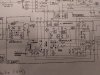
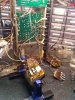
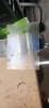
IMG_20200802_094938417.jpg IMG_20200802_095003190.jpg IMG_20200802_095018607.jpg
 
Register to hide this ad
Someones obviously been in there. Make it right.
Those 4.7 fusables can just be wire links, I've seen that from the factory.

Audio grade caps on the protection board? A little strange....
 
This F-2657 has these populated

R13, 10K Ohms, 3W - on my schematic 4.7Ω 3W another Boucherot Cell (?)
R14, 8.1K Ohms, 2W (2.7K in series chain) - on my schematic 4.7Ω 3W another Boucherot Cell (?)
R15, 100 Ohms, ?W - Power meter adjustment dropper resistor (100Ω, 1W)
R16, 100 Ohms, ?W - Power meter adjustment dropper resistor (100Ω, 1W)
R17, 220 Ohms, 5W - Headphone output dropper resistor
R18, 220 Ohms, 5W - Headphone output dropper resistor
R25, 5.2 Ohms, ?W (measured) - on my schematic 10Ω, 3W Boucherot Cell resistor (for stability)
R26, 6.0 Ohms, ?W (measured) - on my schematic 10Ω, 3W Boucherot Cell resistor (for stability)

I read all of those from your posted schematic as well. :confused:

(On F-2657 for 8080DB - on my schematic,they are exactly the same)
 
Last edited:
Hyperion,
Agree with all but can't understand how the R13C09 and R14C10 work as a Boucherot Cell (BC). When the speaker output relay is engaged (up in the schematic) the output of F01/02 (signal high) are directly connected to the speaker selector common via F-2657 01&02 wires. This would mean that the low side of C09/10 would have to be grounded to function as a BC. The schematic shows them bridged back to speaker + (signal high). Must be some sort of filter.

Ivandezande,
Audio grade caps are mine. Seems to be all I buy these days.
 
Well that could be. I was looking a little bit more carefully at the schematic and had this thought. When the relay is Open and the speakers are connected to ground the amplifier is connected through R25C11 & R26C12 and those passive components are shunting any transients to ground. At this point the amplifier is capable of pushing lots of current depending on where the volume control is set. When the relay closes it puts a 4.7 Ohm 3W resistor in series with the capacitor and the speaker and then to ground. Why such a high wattage resistor? Well if you consider an 8 Ohm speaker and an initial inrush current from an amplifier where the volume is set too high then that 3W resistor may be there to dissipate the transient inrush current which is why the capacitor is there to conduct a transient. Any of that make sense?
 
Any of that make sense?
Not entirely.

The capacitor will block DC but pass AC, if the AC signal is large the current can be significant, hence the requirement for a robust resistor. When used in similar locations in 'fast' amplifiers, if they self oscillate, which such amplifiers are prone to do, rather surprisingly those resistors can actually burn up.

If I am correct about the switching transient hypothesis for those particular components they only do their job when the relay opens. However when used in a more conventional sense and location (like the other two pairs), as a Boucherot Cell or (Zobel Network), they are 'in use' all the time.
 
OK, now I see it! The pairs R13C09 and R14C10 are always connected to amplifier power through F01/02 and they find a ground at the series pairs VR01R15 and VR02R16. Which also explains why R15/16 are 1W resistors. Boucherot Cell with a dose of transient protection sounds right.. Thanks.
 
Hello Friends,
Been doing a resto on Ser#816110098 and the F-2657 Power Relay Board has some unusual resistors and it got me thinking.

Schematic says:
R13, 4.7 Ohms, 3W
R14, 4.7 Ohms, 3W
R15, 100 Ohms, 1W
R16, 100 Ohms, 1W
R17, 220 Ohms, 5W
R18, 220 Ohms, 5W
R25, 10 Ohms, 3W
R26, 10 Ohms, 3W

This F-2657 has these populated
R13, 10K Ohms, 3W
R14, 8.1K Ohms, 2W (2.7K in series chain)
R15, 100 Ohms, ?W
R16, 100 Ohms, ?W
R17, 220 Ohms, 5W
R18, 220 Ohms, 5W
R25, 5.2 Ohms, ?W (measured)
R26, 6.0 Ohms, ?W (measured)

Are there factory mods to this board that would support it's current configuration?
And BTW, can someone enlighten me on what the purpose is for each of these resistors pairs?

View attachment 1942741 View attachment 1942742 View attachment 1942743
I have a 9090db .Which I am restoring . The f-2657 board was disassembled. There was a plastic shield there too . Can you tell me how it mounts back in unit.
 

Attachments

  • Sansui 9090db.jpg
    Sansui 9090db.jpg
    49 KB · Views: 16
Back
Top Bottom