A couple of years ago, @kward started this thread:
In response to that thread, I ran a couple of experiments with a 6080 that showed some promise, and then promptly put the idea at the tail of the queue.
Fast-forward to a few weeks ago when the Hafler DH-110 I use in my $DayJob office went on the blink. I had a business trip coming up that involved two 14 hour flights and a bunch of basically free evenings -- i.e. time on my hands. I wasn't going to be able to debug my DH-110 during this time, so I decided to bump the low-gain pre-amp idea to the front of the queue.
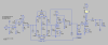
After several iterations, here is what I've come up with. (See attached PDF that contains 3 schematic sheets.)
The circuit consists of 3 basic functional blocks: An input buffer, an active tone stack, and a gain/output stage. The circuit includes a switch that will bypass the tone stack, connecting the output if the input buffer directly to the input of the gain/output stage.
The input buffer exists primarily to isolate the input source from the tone stack. It is a basic MOSFET source-follower using a ZVN0545A. The MOSFET is biased at +125V using voltage divider from the +250V rail.
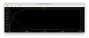
The tone stack consists of a standard 12AX7 inverting gain stage with a negative feedback loop consisting of a Baxandall network. This circuit was adapted from Max Robinson's "Practical Tone Controls" page. The tone stack has roughly unity gain; with the controls set to the flattest response, simulation shows the gain to be approximately -0.35dB. The output of the tone stack is buffered with a direct-coupled ZVN0545A MOSFET source-follower to isolate it from the volume control.
The gain/output stage is a 6AS7 / 6080 power triode loaded with an IXYS 10M45S constant-current source. The output stage is fed by a +160V rail, and the CCS is set for 40mA. This runs the 6AS7 at a very conservative operating point. These are the same conditions I originally ran my experiments with.
The power supply is built around an AnTek AS-05T120 120Vac @ 200mA toroidal power transformer. This transformer also has 2 6.3Vac @ 2A windings, which are paralleled to supply the required 2.8A of heater current. The power supply is rectified using a full-wave voltage doubler. The +160V rail is tapped at the junction of the two capacitors in the doubler and filtered using a CLCLC network employing two Triode C354 (Dynaco ST-70 replacement) filter chokes. The +320V output of the doubler is filtered and brought down to the desired +250V using a CRCRC network.
I originally considered using DC heaters, but after studying Pete Millett's low-mu pre-amp (which allows 6AS7s as one of the tube options) I decided to go with AC heaters biased to +55V. This is taken off the +160V rail with a voltage divider. A 4-turn trim pot is included to zero-out the ripple at the virtual center tap of the heater winding, and a test point is provided on the PSU board for easy scoping when making this adjustment.
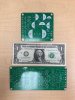
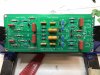
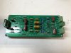
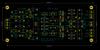
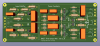
The pre-amp circuit, except for the tube stages, is laid out on a ~6.5" x 2.75" PCB. Connections for the tone control pots are provided by pin headers in the middle of the board. Other connections are made with screw terminals at either end.

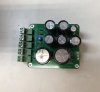
The power supply board measures ~3.75" x 3.25". Because the 6AS7 is run from a +160V rail, the capacitors are physically pretty small.
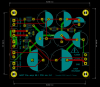
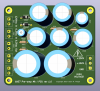
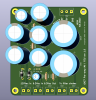
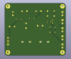
(Please excuse the visual hiccups on the PCB back-side renderings ... I had to create some new footprints in KiCad for some of the capacitors, based on other footprints in KiCad's standard footprint library, and I neglected to update the 3D models.)
The CCS for both channels are located on a separate generic board I made for this purpose. The details of that board's circuit are not detailed on this schematic -- I build up some boards for that as a separate generic component.
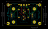
I should be receiving the pre-amp circuit and PSU PCBs from the fabricator on Monday, and I intend to document the build in this thread. At the end of the process, I'll be making all of the design files available, including Gerbers suitable for sending to your favorite PCB fabricator.
In a follow-up post later today, I'll be sharing some of the simulation data for the pre-amp circuit.
In response to that thread, I ran a couple of experiments with a 6080 that showed some promise, and then promptly put the idea at the tail of the queue.
Fast-forward to a few weeks ago when the Hafler DH-110 I use in my $DayJob office went on the blink. I had a business trip coming up that involved two 14 hour flights and a bunch of basically free evenings -- i.e. time on my hands. I wasn't going to be able to debug my DH-110 during this time, so I decided to bump the low-gain pre-amp idea to the front of the queue.
After several iterations, here is what I've come up with. (See attached PDF that contains 3 schematic sheets.)
The circuit consists of 3 basic functional blocks: An input buffer, an active tone stack, and a gain/output stage. The circuit includes a switch that will bypass the tone stack, connecting the output if the input buffer directly to the input of the gain/output stage.
The input buffer exists primarily to isolate the input source from the tone stack. It is a basic MOSFET source-follower using a ZVN0545A. The MOSFET is biased at +125V using voltage divider from the +250V rail.
The tone stack consists of a standard 12AX7 inverting gain stage with a negative feedback loop consisting of a Baxandall network. This circuit was adapted from Max Robinson's "Practical Tone Controls" page. The tone stack has roughly unity gain; with the controls set to the flattest response, simulation shows the gain to be approximately -0.35dB. The output of the tone stack is buffered with a direct-coupled ZVN0545A MOSFET source-follower to isolate it from the volume control.
The gain/output stage is a 6AS7 / 6080 power triode loaded with an IXYS 10M45S constant-current source. The output stage is fed by a +160V rail, and the CCS is set for 40mA. This runs the 6AS7 at a very conservative operating point. These are the same conditions I originally ran my experiments with.
The power supply is built around an AnTek AS-05T120 120Vac @ 200mA toroidal power transformer. This transformer also has 2 6.3Vac @ 2A windings, which are paralleled to supply the required 2.8A of heater current. The power supply is rectified using a full-wave voltage doubler. The +160V rail is tapped at the junction of the two capacitors in the doubler and filtered using a CLCLC network employing two Triode C354 (Dynaco ST-70 replacement) filter chokes. The +320V output of the doubler is filtered and brought down to the desired +250V using a CRCRC network.
I originally considered using DC heaters, but after studying Pete Millett's low-mu pre-amp (which allows 6AS7s as one of the tube options) I decided to go with AC heaters biased to +55V. This is taken off the +160V rail with a voltage divider. A 4-turn trim pot is included to zero-out the ripple at the virtual center tap of the heater winding, and a test point is provided on the PSU board for easy scoping when making this adjustment.
The pre-amp circuit, except for the tube stages, is laid out on a ~6.5" x 2.75" PCB. Connections for the tone control pots are provided by pin headers in the middle of the board. Other connections are made with screw terminals at either end.
The power supply board measures ~3.75" x 3.25". Because the 6AS7 is run from a +160V rail, the capacitors are physically pretty small.
(Please excuse the visual hiccups on the PCB back-side renderings ... I had to create some new footprints in KiCad for some of the capacitors, based on other footprints in KiCad's standard footprint library, and I neglected to update the 3D models.)
The CCS for both channels are located on a separate generic board I made for this purpose. The details of that board's circuit are not detailed on this schematic -- I build up some boards for that as a separate generic component.
I should be receiving the pre-amp circuit and PSU PCBs from the fabricator on Monday, and I intend to document the build in this thread. At the end of the process, I'll be making all of the design files available, including Gerbers suitable for sending to your favorite PCB fabricator.
In a follow-up post later today, I'll be sharing some of the simulation data for the pre-amp circuit.