I need another power amplifier like I need a hole in my head. But as I have "matured" in my audio years, the ever imbedded Tim Taylor motto of "Mo' Power!" has begun to wane in me. 100+ db efficient speakers has so often left me asking why have so much power? I know all the arguments, but even when I crank 38 Special's Hold on Loosely with the bass boosted, or let some of Bach's organ pieces dust the ceiling fans, the power peaks rarely eclipse 10 watts per channel. My typical listening power (i.e., 98% of the time) barely reaches a couple of watts per channel. I've got big tube power, and it's great stuff. But to have it idle at a power output of maybe a couple of watts while dissipating 75 times or more that amount of power in heat virtually all the time is sorta crazy, from any one of a number of angles. So, while the big stuff will always be a part of me, as long as my speakers are as efficient as they are, ratcheting things down a bit makes a lot of sense for me. But just because the power is turned down, I still want the sound itself to be just as big.
Lower power in this case means a good 15 to 20 watts RMS in both channels. When other factors are plugged into the equation, that ultimately equates for me to the 6BQ5 family of tubes, in some form of push-pull configuration. Now each will have their own favorite as to just which amp constitutes their favorite pump house with these tubes. But for me, the short list (in no particular order) includes the Dynaco ST-35, Fisher SA-100, and Heathkit AA-30, because they have the best goods to deliver the best goods. Heathkit offered a face lifted version of the AA-30 as the AA-111, but other than the appearance change, the circuit and build of the two units are identical in every respect. Between them, my personal preference is for the AA-30, as the gold and black color scheme makes for a darn good lookin' unit in a small package.
Within the short list, I already have a superb ST-35, and an equally worthy clone of the SA-100, which some may remember as a project over on the Fisher Forum. But a basic stereo power amplifier in this power range from Heathkit has been missing from my stable. When one became available recently at auction then, I pounced on it. It was in decent physical shape, came complete with the cover and original manual, and was even located close by so I could pick it up. Heck, even the goofy plastic feet were all in tact! For the most part, it was even operational.
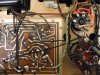
A quick once over showed that the circuit boards had certainly been rode hard and put up wet from all the heat they had endured over time, and from some less than careful previous service efforts as well. Otherwise however, the unit was well built according to the pics and directions in the Heath manual. And, the previous owner had already replaced a number of caps and resistors throughout the unit, so component tolerance was not a problem. Ultimately then, once a really weak output tube and a couple of bum coupling caps were replaced, the unit was ready for both lab and sonic testing. The results from those efforts were quickly made clear to me: While the general sound was good, there were other aspects of the unit that were easily evident in both the lab and listening setting, that were completely unacceptable to me.
A web search returned the usual threads of bringing one of these units back from the dead, general trouble shooting, or discussing which components sounded best in them. But none of them mention or address the general shortcomings I noted with my unit. Shortcomings, that were not the result of a poor build or bad components, but rather were simply a product of the basic design/layout of the unit, and therefore would be present in all such units.
Against that however, because there is SO much potential for these units, and because the AA-30 is such a good looking "right size" unit for me, I decided to go all out after all the issues I noted. The results have been nothing short of stellar -- truly transformational, putting a high gloss polish on a rough stone. I will present the issues noted in laundry list form in this post, and use succeeding posts to address the resolve devised for each. The issues can be grouped into two basic areas: Hum, and Everything Else.
With 101 db (Cornwall) speakers, and a typical preamp (Fisher 400C) to drive the AA-30, the quiescent hum from my listening position some 10 ft away was intolerable, as it was easily/readily apparent. To me, ANY quiescent hum that can be heard at the listening position is unacceptable, as then it becomes part of the overall presentation. Frankly, the only quiescent noise I want to hear is a soft hiss, apparent only when the ear is within literally inches of the speaker board. Any type of quiescent noise that can be heard at the listening position then is completely unacceptable.
The hum in this unit was made up of a variety of types, and therefore, was produced from a variety of design concerns. The hum noted consisted of:
1. Excessive 120 Hz Hum:
Especially notable when first turned on. This always calmed down when the output tubes were fully warmed, but never completely went away. Even with well matched output tubes, the noise was ever present. Filter caps were not the basis of this noise.
2. Excessive Ground Loop Hum:
This was particularly problematic, in that simply connecting a turned off, unplugged preamp to the input jacks caused a notable increase in ground loop hum, that could only be reduced by either lifting the ground connection of one of the interconnects (either channel, by only partially inserting the plug), or by turning both gain controls to minimum. The latter approach of course results in no music, while the former approach is dangerous if the ground connection within the one interconnect providing the ground connection becomes compromised. It can and does happen. This made up the majority of the total hum produced.
3. Excessive Left Channel Hum -- (especially at partial level control settings)
Between all three of these issues, this unit could hum a tune all by itself, even without a little help from its friends. Actually, Heath was aware of the general noise concern as well, as evidenced by the rather dismal Hum and Noise specification of 76 db below 14 watts.
As for Everything Else:
4. The AA-30 has excessive gain (requiring just .74 vac to produce 14 watts), elevating the quiescent hiss level when a preamp is connected, and causing the volume control on a typical preamp to operate "down in the weeds". Of course, the gain controls on the AA-30 can be backed off -- but here comes more hum in the left channel if you do, and compromised HF response in both channels as well.
5. In the lab, the AA-30 has visibly excessive 10 kHz square wave ringing. Again, this was not due to component/build issues, but simply was the product of the design. Poor transient stability (as evidenced by by excessive ringing) is almost always a sure sign of poor overall HF stability as well.
6. Surprise, surprise. A cap only load of just over .05 uF caused either channel to go ballistic (produce outright high power oscillation). This is really bad behavior. For OPTs that are otherwise of very superior performance, this was a major disappointment of the design.
So again, for such a promising unit, the excessive hum, noise, ringing, and stability issues left my AA-30 coming off like a rank amateur, against the polished presentation of its other stall mates. Fortunately, they can all be resolved -- starting next time.
Dave