Alessioave
New Member
Hi everyone, it is my first post and hopefully it is in the right section of the forum.
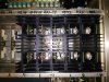
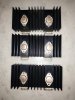
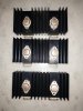
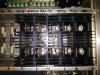
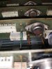
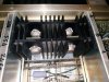
I have since long time, this amplifier, A&E technical research DCA 400, that recently give up on one channel, 5 output transistors. I took off the top plate to check it, after some smoke came up from the right part of the chassis wile messing with some loudspeakers wires. Unfortunately I tryed to look for the service manual on sites like hifiengine etc. but without luck. It looks pretty strate forward concerning the design ( I can post pictures if somebody it is interested). After taking off all the heatsinks ( they are removable, ) 10 aluminum plates with 2 bipolar transistors on each heatsinks 8 row of output and 2 row of drivers. They are looking like original Toshiba 2sc2460a 2 of them are gone) and the 2sa1050a ( 3 of them give up) . I could not find a source for those Toshiba transistors at list in Italy were I am located. Reading on this precious forum about some other amplifers using the same types of Toshiba transistors, (Yamaha m4 etc.) I went on and ordered 4 couples of MJ2193 and MJ2194 transistors recommended by others for the above mentioned amplifiers. My intention is to replace all of the Toshiba PNP transistors in one channel and see what happens. I checked all the resistors and replaced few capacitors looking a bit weak or out of specs. The rest, fuses, line caps, transformer, diodes looked and tested allright. Any help in finding the service manual or any help in general is highly appreciated. I was already able to fix a nice Phase Linear 400 series 2 that burned few output transistors reading the helpful posts on this forum and also with the help of some ex employee of Phase Linear ( Bob Carver era), kind enough to guide me through the testing of the 400. I hope I can bring back to life this one too. If you are interested in the specs there Is an old page not updated since 2012, withspecs and pics ( not to bad for the 70s) at this link:
http://www.applisacc.jp/gamisun/aande/index.cgi?ms=01100802
Thanks in advance.
I have since long time, this amplifier, A&E technical research DCA 400, that recently give up on one channel, 5 output transistors. I took off the top plate to check it, after some smoke came up from the right part of the chassis wile messing with some loudspeakers wires. Unfortunately I tryed to look for the service manual on sites like hifiengine etc. but without luck. It looks pretty strate forward concerning the design ( I can post pictures if somebody it is interested). After taking off all the heatsinks ( they are removable, ) 10 aluminum plates with 2 bipolar transistors on each heatsinks 8 row of output and 2 row of drivers. They are looking like original Toshiba 2sc2460a 2 of them are gone) and the 2sa1050a ( 3 of them give up) . I could not find a source for those Toshiba transistors at list in Italy were I am located. Reading on this precious forum about some other amplifers using the same types of Toshiba transistors, (Yamaha m4 etc.) I went on and ordered 4 couples of MJ2193 and MJ2194 transistors recommended by others for the above mentioned amplifiers. My intention is to replace all of the Toshiba PNP transistors in one channel and see what happens. I checked all the resistors and replaced few capacitors looking a bit weak or out of specs. The rest, fuses, line caps, transformer, diodes looked and tested allright. Any help in finding the service manual or any help in general is highly appreciated. I was already able to fix a nice Phase Linear 400 series 2 that burned few output transistors reading the helpful posts on this forum and also with the help of some ex employee of Phase Linear ( Bob Carver era), kind enough to guide me through the testing of the 400. I hope I can bring back to life this one too. If you are interested in the specs there Is an old page not updated since 2012, withspecs and pics ( not to bad for the 70s) at this link:
http://www.applisacc.jp/gamisun/aande/index.cgi?ms=01100802
Thanks in advance.
Last edited: